
User guide

22 Rockwell Automation Publication 1768-UM002C-EN-P - April 2012
Chapter 2 Install the Controller
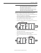
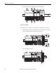
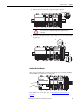
• Up to eight 1769 Compact I/O modules can reside on each side of a 1769
power supply in a remote bank. Consult the module’s specifications for its
distance rating.
• The type of controller determines the maximum number of 1768 modules
that can reside in the local bank and the maximum number of 1769 I/O
modules that can reside in one local and up to two remote banks.
Mount the Controller
You can mount the controller to a panel or on a DIN rail.
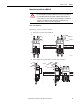
Panel Mount the Controller
Follow these steps to mount your controller by using the panhead screws.
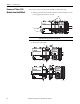
1. Connect the CompactLogix modules together as shown in Mount the
Controller on a DIN Rail on page 23.
2. Use the controller as a template and mark pilot holes on your panel.
3. Drill the pilot holes for M4 or #8 screws.
4. Use M4 or #8 screws to mount the controller to your panel with 1.16 N•m
(10 lb•in) of torque.
5. Ground the module on a ground bus with a dedicated earth ground stake.
6. Connect the ground bus to a functional earth ground on the panel or a
DIN rail.
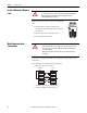
IMPORTANT
1769 power supplies must be separated from the 1768 series
processor by a bus extension cable. Never put a 1769 power supply in
the 1768 backplane or the controller will generate a major fault that
cannot be cleared until you remove the 1769 power supply.
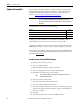
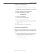
Controller Max Local 1768 Modules Max 1769 I/O Modules (local and remote)
1768-L43S 2 16
1768-L45S 4 30
IMPORTANT
Do not use screws if using a DIN rail to mount the controller. You can
break the mounting tabs if you screw the controller to a panel while it
is on a DIN rail.
ATTENTION: During mounting of all devices, be sure that all debris
(such as metal chips or wire strands) is kept from falling into the
controller or I/O modules. Debris that falls into the controller or
modules could cause damage while the controller is energized.