Installation Instructions CompactLogix Controllers Catalog Numbers 1768-L43, 1768-L43S, 1768-L45, 1768-L45S Topic Page Important User Information 2 About CompactLogix Controllers 6 Verify Compatibility 6 Required System Components 7 Clearance Requirements 7 Module Placement 8 Install the Controller 9 Panel Mount the Controller 10 Mount the Controller on a DIN Rail 10 Confirm the Installation 13 Connect to the Controller 14 Configure a Communication Driver 14 Insert or Remove a Com
CompactLogix Controllers Important User Information Solid state equipment has operational characteristics differing from those of electromechanical equipment. Safety Guidelines for the Application, Installation and Maintenance of Solid State Controls (publication SGI-1.1 available from your local Rockwell Automation sales office or online at http://literature.rockwellautomation.com) describes some important differences between solid state equipment and hard-wired electromechanical devices.
CompactLogix Controllers 3 Environment and Enclosure ATTENTION This equipment is intended for use in a Pollution Degree 2 industrial environment, in overvoltage Category II applications (as defined in IEC publication 60664-1), at altitudes up to 2000 m (6562 ft) without derating. This equipment is considered Group 1, Class A industrial equipment according to IEC/CISPR Publication 11.
CompactLogix Controllers European Hazardous Location Approval Consider the following if you install a 1768-L43S or 1768-L45S controller in a European Zone 2 location. European Zone 2 Certification (The following applies when the product bears the EX marking.
CompactLogix Controllers 5 North American Hazardous Location Approval The following information applies when operating this equipment in hazardous locations. Informations sur l’utilisation de cet équipement en environnements dangereux. Products marked "CL I, DIV 2, GP A, B, C, D" are suitable for use in Class I Division 2 Groups A, B, C, D, Hazardous Locations and nonhazardous locations only.
CompactLogix Controllers About CompactLogix Controllers CompactLogix 1768-L43 and 1768-L45 controllers are designed to provide a Logix solution for medium-sized applications. Compact GuardLogix controller catalog numbers end in ‘S’. These safety controllers are wider than their standard counterparts.
CompactLogix Controllers 7 Required System Components You need these parts when installing your controller: • 1768-L43, 1768-L43S, 1768-L45, or 1768-L45S CompactLogix controller • 1768-PA3 or 1768-PB3 power supply • 1769-ECR end cap • Mounting screws (M4 or #8 panhead) or one of these EN 50 022 DIN rails: – 35 x 7.5 mm (1.38 x 0.30 in.) – 35 x 15 mm (1.38 x 0.59 in.
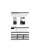
CompactLogix Controllers Module Placement 1768 Backplane (local) 1768 Controller, Power Supply, and I/O Modules Remote Bank 1769 Power Supply and I/O Modules 1769 Backplane IMPORTANT CompactLogix System Distance Ratings Because the 1768 CompactLogix power supply works with the controller to power a 1768 system, the distance rating in a 1768 CompactLogix system differs from that in a 1769 CompactLogix system.
CompactLogix Controllers 9 • Up to eight 1769 Compact I/O modules can reside on each side of a 1769 power supply in a remote bank. Consult the module’s specifications for its distance rating. IMPORTANT Never place a 1769 power supply in a local bank with a 1768 controller or a major fault will occur. • The type of controller determines the maximum number of 1768 modules that can reside in the local bank and the maximum number of 1769 I/O modules that can reside in one local and up to two remote banks.
CompactLogix Controllers Panel Mount the Controller Follow these steps to mount your controller by using the panhead screws. 1. Connect the CompactLogix modules together as shown in Mount the Controller on a DIN Rail on page 10. 2. Use the controller as a template and mark pilot holes on your panel. 3. Drill the pilot holes for M4 or #8 screws. ATTENTION During mounting of all devices, be sure that all debris (such as metal chips or wire strands) is kept from falling into the controller or I/O modules.
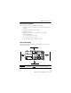
CompactLogix Controllers 11 Mount 1768 Components Follow these steps to mount the controller. 1. Mount the controller on the DIN rail. a. b. 31595-M 31596 -M 2. Mount additional 1768 modules to the left of the controller. c. a. b. a. 31597-M c. 31598 -M 3. Mount the 1768 power supply and other 1768 modules.
CompactLogix Controllers Mount 1769 I/O Modules Follow these steps to mount 1769 I/O modules to the right of the controller. 1. Align the upper and lower tongue-and-groove slots and slide the module back toward the DIN rail until the bus levers line up. 2. Close the DIN rail latches. 3. Slide the bus lever to the left to lock the modules together. ATTENTION When attaching I/O modules, it is very important that the bus connectors are securely locked together for proper electrical connection.
CompactLogix Controllers 13 4. Attach the end cap by using the tongue and groove slots (a) and locking the bus lever (b). a. b. a. Confirm the Installation After you have installed the controller and applied power, check that the PWR and I/O PWR status indicators are solid green. Power OUT L1 L2/N If the indicators are in any other state, see Troubleshoot System Power on page 28.
CompactLogix Controllers Connect to the Controller WARNING If you connect or disconnect the serial cable with power applied to this module or the serial device on the other end of the cable, an electrical arc can occur. This could cause an explosion in hazardous location installations. Be sure that power is removed or the area is nonhazardous before proceeding. Connect the 1756-CP3 serial cable to the controller’s serial port and to your workstation.
CompactLogix Controllers 15 Configure a Serial Driver Use RSLinx software to configure the driver for serial communication. 1. From the Communications menu, choose Configure Drivers. 2. From the Available Driver Types pull-down menu, choose the RS-232 DF1 devices driver. 3. Click Add New. 4. Type a name for the driver and click OK.
CompactLogix Controllers 5. From the Comm Port pull-down menu on the Configure Devices dialog box, choose the serial port on the workstation to which your cable is connected. 6. From the Device pull-down menu, choose Logix5550/CompactLogix. 7. Click Auto-Configure. a. Click OK if the Auto Configuration Successful dialog box appears. b. If the dialog box does not appear, go back to step 5 and verify that you selected the correct comm port. 8. Click Close.
CompactLogix Controllers 17 Configure an EtherNet/IP Driver For EtherNet/IP communication, you must use a 1768-ENBT or 1768-EWEB module. If your controller is a 1768-L4xS, you must use a series B 1768-ENBT or 1768-EWEB module. You can install up to two of these modules to the left of the controller in the 1768 backplane. Before you can load controller firmware via the EtherNet/IP network, you must set the EtherNet/IP module’s IP address.
CompactLogix Controllers Insert or Remove a CompactFlash Card WARNING When you insert or remove the CompactFlash card while power is on, an electrical arc can occur. This could cause an explosion in hazardous location installations. Be sure that power is removed or the area is nonhazardous before proceeding. Follow these steps to insert or remove a CompactFlash card. 1. Press the memory-card door latch on the controller front panel and pivot the door down toward you. 2.
CompactLogix Controllers 19 Updating your controller firmware via ControlFlash or AutoFlash software requires either a serial or other network connection to the controller. Updating via an Ethernet connection is faster, but you must first install a 1768-ENBT Ethernet module to connect to the controller via the Ethernet network. For information on installing, configuring, and operating a 1768-ENBT module, refer to the EtherNet/IP Modules in Logix5000 Control Systems User Manual, publication ENET-UM001.
CompactLogix Controllers Install Firmware via AutoFlash Software 1. Make sure the network is connected. 2. Using RSLogix 5000 software, attempt a download to a controller project. AutoFlash software launches if the required firmware is not loaded on the controller. 3. Select the catalog number of the controller and click Next. 4. Expand the network until you see the controller. TIP If the required network is not shown, first configure a driver for that network in RSLinx software. 5.
CompactLogix Controllers 21 Install Firmware via a CompactFlash Card Follow these steps to use RSLogix 5000 software to store the controller program and firmware of an already-configured controller to the CompactFlash card. The firmware is automatically stored on your CompactFlash card when you store the program. 1. With the CompactFlash card installed on the configured controller, on the Controller Properties dialog box, click the Nonvolatile Memory tab. 2. Click Load Image On Powerup to save to the card.
CompactLogix Controllers 2. Remove the 1768 module. a. b. Power OUT L1 L2/N a. d. c. Power O UT L1 L 2 /N c. 31607-M 3. Remove the 1769 module by unlocking the bus lever (a) and DIN rail latches (b). b. a. Power OUT L1 L2/N b. 4. Slide the module away from the DIN rail along the tongue and groove slots.
CompactLogix Controllers 23 Status Indicators Controller Status Indicators Indicator State Description Green The controller is providing power to 1768 modules in the system. PWR I/O PWR RUN FORCE MEM SAVE I/O Off or red See Troubleshoot System Power on page 28. Off Replace the controller. Green The controller is operating properly. Flashing red/green or solid red See Troubleshoot System Power on page 28. Off The controller is in PROG or Test mode. Green The controller is in RUN mode.
CompactLogix Controllers Controller Status Indicators Indicator State Description OK Off No power is applied. If MEM SAVE indicator is green, the user program and configuration data are being saved to flash memory. Flashing red • The controller requires a firmware update or a firmware update is in progress. • A recoverable major fault occurred on the controller. • A nonrecoverable major fault occurred on the controller. • See Clear a Major Fault on page 26.
CompactLogix Controllers 25 Safety Status Indicators (1768-L43S and 1768-L45S Controllers only) Indicator State Description Off The user safety task or safety outputs are disabled. The controller is in PROG mode, Test mode, or the safety task is faulted. Green The user safety task and safety outputs are enabled. The safety task is executing. Safety signature is present. Flashing green The user safety task and safety outputs are enabled. The safety task is executing. Safety signature is not present.
CompactLogix Controllers Clear a Major Fault If the OK status indicator flashes red because of a recoverable major fault, clear the fault by following these steps. 1. Turn the controller keyswitch from PROG to RUN and back to PROG. 2. Go online with RSLogix 5000 software. 3. On the Controller Properties dialog box, click the Major Faults tab to find information about the fault.
CompactLogix Controllers 27 Clear a Nonrecoverable Fault If the OK status indicator is solid red, follow these steps to clear the fault. 1. Cycle power. 2. Download the project. 3. Change to REM RUN or RUN mode. If the issue persists, record the status of the OK and RS-232 indicators before cycling power and contacting Rockwell Automation support. Troubleshoot a Nonresponsive Module Follow these steps to determine why a device may not be responding. 1.
CompactLogix Controllers Troubleshoot System Power The CompactLogix power supply works with the CompactLogix controller to provide power to the system. You must consider both when attempting to troubleshoot system power. IMPORTANT Before you disconnect, reconnect, or replace any component, make sure you have turned off power and allowed all system status indicators to turn off.
CompactLogix Controllers 29 Examine the Power Supply PWR Status Indicator Power Supply PWR Indicator Status Recommended Action Off Verify that the power supply is turned on and that adequate input power is properly connected. Replace the power supply. Green The power supply is operating properly. Check the controller PWR and I/O PWR status indicators to make sure the entire system is operating properly. Red The power supply is not producing valid 24V power to the 1768 modules.
CompactLogix Controllers Examine the Controller PWR Indicator This task assumes that the power supply PWR indicator is green. Controller PWR Indicator Status Recommended Action Off Make sure all of the modules in the system are installed properly and are fully engaged with one another. If the indicator remains off, follow the corrective action below. Green The controller is providing power to 1768 modules in the system.
CompactLogix Controllers 31 Examine the I/O PWR Indicator This task assumes that the power supply and controller PWR indicators are green and that you have 1769 I/O modules in your system. Controller I/O PWR Recommended Action Indicator Status(1) Off Replace the controller. Green The controller is operating properly. No action required. Flashing red and green Make sure the 1769 I/O modules or end cap are properly attached and cycle power.
CompactLogix Controllers Specifications 1768-L43, 1768-L43S, 1768-L45, 1768-L45S Controllers Attribute 1768-L43 1768-L43S 1768-L45 1768-L45S 1768 backplane module support 2 Backplane current 1.3 A @ 24V 1769 backplane current output 2.0 A @ 5.2V 2.0 A @ 5.2V 1768 backplane current output 2.8 A @ 5.2V 5.6 A @ 5.2V Total 1768 and 1769 backplane current output 4.8 A @ 5.2V 7.6 A @ 5.2V Power dissipation 6.3 W(2) 7.5 W(2) 8.3 W(2) 9.5 W(2) Power consumption 31.3 W 33.6 W 48.
CompactLogix Controllers 33 1768-L43, 1768-L43S, 1768-L45, 1768-L45S Controllers Attribute 1768-L43 1768-L43S 1768-L45 1768-L45S Dimensions (HxWxD), approx. 131.6 x 67.4 x 121.8 mm (5.18 x 2.65 x 4.80 in.) 131.6 x 90 x 121.8 mm (5.18 x 3.55 x 4.80 in.) 131.6 x 67.4 x 121.8 mm (5.18 x 2.65 x 4.80 in.) 131.6 x 90 x 121.8 mm (5.18 x 3.55 x 4.80 in.) Weight, approx. 0.34 kg (11.9 oz) 0.45 kg (15.9 oz) 0.34 kg (11.9 oz) 0.45 kg (15.
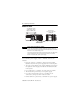
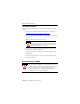
CompactLogix Controllers 1768-L45 and 1768-L45S Power Dissipation 9.5 W 4.0 W Power Dissipated (Watts) 2.8 W 8 8.3 W 6 4 1768-L45S 2 0 1768-L45 5 10 15 20 25 30 35 40 1768 and 1769 Bus 5.2V Load (Watts) Environmental Specifications Attribute Value Temperature, operating IEC 60068-2-1 (Test Ad, Operating Cold), IEC 60068-2-2 (Test Bd, Operating Dry Heat), IEC 60068-2-14 (Test Nb, Operating Thermal Shock): 0...60 °C (32...
CompactLogix Controllers 35 Environmental Specifications Attribute Value Radiated RF immunity IEC 61000-4-3: 10V/m with 1 kHz sine-wave 80% AM from 80…2000 MHz 10V/m with 200 Hz 50% Pulse 100% AM @ 900 MHz 10V/m with 200 Hz 50% Pulse 100% AM @ 1890 MHz 3V/m with 1 kHz sine-wave 80% AM from 2000…2700 MHz Surge transient immunity IEC 61000-4-5: ±2 kV line-earth (CM) on communication ports Conducted RF immunity IEC 61000-4-6: 10V rms with 1 kHz sine-wave 80%AM from 150 kHz…80 MHz Certifications (when p
Additional Resources These documents contain additional information concerning related Rockwell Automation http://www.ab.com products. Resource Description EtherNet/IP Modules in Logix5000 Control Systems User Manual, publication ENET-UM001 Details how to configure, program, operate, and troubleshoot EtherNet/IP modules, and provides technical specifications.