768 CompactLogix System Catalog Numbers 1768-L43 and 1768-L45 CompactLogix Controllers Quick Start
Important User Information Solid state equipment has operational characteristics differing from those of electromechanical equipment. Safety Guidelines for the Application, Installation and Maintenance of Solid State Controls (publication SGI-1.1 available from your local Rockwell Automation sales office or online at http://www.rockwellautomation.com/literature/) describes some important differences between solid state equipment and hard-wired electromechanical devices.
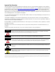
Where to Start Follow the path that matches your hardware and network configuration.
Where to Start How Hardware Is Connected This quick start demonstrates CompactLogix L43 and L45 control systems using a single EtherNet/IP or DeviceNet network for cost-effectiveness and simplified setup. You may choose to use a multiple network system requiring a combination of EtherNet/IP and DeviceNet procedures shown in this quick start. Rockwell Automation also offers many devices other than those in the examples. See your local Rockwell Automation representative for other device options.
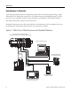
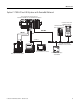
Where to Start Option 2: 1768-L43 and L45 Systems with DeviceNet Network 1768-L43 CompactLogix Controller with 1768-M04SE SERCOS and 1769-SDN DeviceNet Modules PowerFlex 70 Drive with 20-COMM-D Adapter Distributed POINT I/O with 1734-ADN Adapter DeviceNet SERCOS Serial 2706-NC13 1756-CP3 DeviceNet with KwikLink flat cable and micro connectors 2094 Kinetix 6000 Multi-axis Servo Drive System Computer Publication IASIMP-QS003B-EN-P - October 2009 2711P PanelView Plus Terminal DeviceNet Power Supply 1606
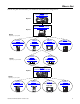
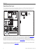
Where to Start Sample System Panel Layout The sample panel layout shows the general orientation of 1768-L43 and 1768-L45 system components for both EtherNet/IP and DeviceNet networks used in this quick start.
Table of Contents Preface About This Publication . . . . . . . . . . . . . . . . . . . . . . . . . . . . . . . . . . . . . 13 Audience . . . . . . . . . . . . . . . . . . . . . . . . . . . . . . . . . . . . . . . . . . . . . . . . . 14 Required Software . . . . . . . . . . . . . . . . . . . . . . . . . . . . . . . . . . . . . . . . . 14 Parts List: Option 1, 1768-L43 System with EtherNet/IP . . . . . . . . . 15 Parts List: Option 2, 1768-L43 System with DeviceNet . . . . . . . . . . . 17 Conventions . . . .
Table of Contents Chapter 4 Prepare the PowerFlex 70 Drive Introduction . . . . . . . . . . . . . . . . . . . . . . . . . . . . . . . . . . . . . . . . . . . . . . 61 Before You Begin. . . . . . . . . . . . . . . . . . . . . . . . . . . . . . . . . . . . . . . . . . 61 What You Need . . . . . . . . . . . . . . . . . . . . . . . . . . . . . . . . . . . . . . . . . . . 61 Follow These Steps . . . . . . . . . . . . . . . . . . . . . . . . . . . . . . . . . . . . . . . .
Table of Contents Chapter 8 Configure the DeviceNet Network Introduction . . . . . . . . . . . . . . . . . . . . . . . . . . . . . . . . . . . . . . . . . . . . . . 93 Before You Begin. . . . . . . . . . . . . . . . . . . . . . . . . . . . . . . . . . . . . . . . . . 93 What You Need . . . . . . . . . . . . . . . . . . . . . . . . . . . . . . . . . . . . . . . . . . . 93 Follow These Steps . . . . . . . . . . . . . . . . . . . . . . . . . . . . . . . . . . . . . . . .
Table of Contents Chapter 11 Create a PowerFlex 70 Application Introduction . . . . . . . . . . . . . . . . . . . . . . . . . . . . . . . . . . . . . . . . . . . . . 137 Before You Begin. . . . . . . . . . . . . . . . . . . . . . . . . . . . . . . . . . . . . . . . . 137 What You Need . . . . . . . . . . . . . . . . . . . . . . . . . . . . . . . . . . . . . . . . . . 137 Follow These Steps . . . . . . . . . . . . . . . . . . . . . . . . . . . . . . . . . . . . . . .
Table of Contents Appendix A Network Information Network Information. . . . . . . . . . . . . . . . . . . . . . . . . . . . . . . . . . . . . . 197 Appendix B Kinetix Accelerator Toolkit Sample Panel Layout . . . . . . . . . . . . . . . . . . . . . . . . . . . . . . . . . . . 199 Simplified Wiring . . . . . . . . . . . . . . . . . . . . . . . . . . . . . . . . . . . . . . 199 Preconfigured HMI . . . . . . . . . . . . . . . . . . . . . . . . . . . . . . . . . . . . 199 Preconfigured Logic. . . . . . . .
Table of Contents 12 Publication IASIMP-QS003B-EN-P - October 2009
Preface About This Publication This quick start provides examples and procedures for 1768-L43 and 1768-L45 CompactLogix systems. It includes version 18 release updates for RSLogix 5000 programming software. These procedures cover many common user tasks, such as: • connecting the controller to multiple devices including local and distributed I/O, drives, Kinetix 6000 servo drives, and a PanelView Plus terminal.
Audience This quick start was created to assist experienced or new industrial control users not familiar with the CompactLogix controllers or Integrated Architecture products of Rockwell Automation. Required Software The table lists software required to complete the examples in this quick start. Some software is required regardless of the 1768 CompactLogix system you use and other software is dependent on the network and devices in the system.
Parts List: Option 1, 1768-L43 and 1768-L45 Systems with EtherNet/IP The table lists the parts for the 1768-L43 and 1768-L45 systems with an EtherNet/IP network and a 200/230V Kinetix 6000 Multi-axis Servo Drive System.
Parts List: Option 1, 1768-L43 and 1768-L45 Systems with EtherNet/IP Network Quantity Catalog Number Description Kinetix 6000 Servo Drive System - 200/230V (The quantity, size, and cat. nos. for the Kinetix equipment will vary by application motion requirements.) 1 1768-M04SE SERCOS interface module installs in 1768 CompactLogix controller and connects to Integrated Axis modules or Axis modules.
Parts List: Option 2, 1768-L43 and 1768-L45 Systems with DeviceNet The table lists the parts for a 1768-L43 and 1768-L45 Systems with DeviceNet I/O, serial connections, and a 200/230V Kinetix 6000 Multi-axis Servo Drive System.
Parts List: Option 2, 1768-L43 and 1768-L45 Systems with DeviceNet Network Quantity Catalog Number Description Kinetix 6000 Servo Drive System - 200/230V (The quantity, size, and cat. nos. for the Kinetix equipment will vary by application motion requirements.) 1 1768-M04SE SERCOS interface module installs in 1768 CompactLogix controller and connects to Integrated Axis modules or Axis modules.
Conventions This manual uses the following conventions. Convention Meaning Example Courier font Type or enter text exactly as shown. Type cmd. Check or uncheck Click to activate or deactivate a checkbox. Check the Disable Keying checkbox. Click Click the left mouse button once while the cursor is positioned on object or selection. Click Browse. Double-click Click the left mouse button twice in quick succession while the cursor is positioned on object or selection.
Notes: 20 Publication IASIMP-QS003B-EN-P - October 2009
Chapter 1 Prepare the CompactLogix Hardware Introduction In this chapter, you install your CompactLogix hardware including the controller, power supply, 1768 SERCOS module, and the 2094 line interface module. The line interface module will power the 1768 CompactLogix and Kinetix 6000 system components. Depending on your configuration, you also install the 1768 EtherNet/IP module, 1769 DeviceNet module, and local 1769 I/O modules. Before You Begin Determine which network and appropriate hardware to use.
Chapter 1 Prepare the CompactLogix Hardware Follow These Steps Complete the appropriate steps to assemble your 1768-L43/L45 CompactLogix hardware.
Prepare the CompactLogix Hardware Chapter 1 About the 1768 CompactLogix Controller The 1768-L43 and 1768-L45 CompactLogix controllers combine a 1768 backplane and a 1769 backplane. The 1768 backplane supports the 1768 controller, the 1768 power supply, and a maximum of two 1768 modules, such as the EtherNet/IP module and the SERCOS interface module. The 1769 backplane supports 1769 modules, such as the 1769 DeviceNet module and 1769 I/O modules.
Chapter 1 Prepare the CompactLogix Hardware Mount and Wire the Line Interface Module 2094-AL75S or Equivalent Hardware, Required for EtherNet/IP and DeviceNet Systems The line interface module (LIM) serves as the power connection and the generation point for the complete power needs of most control panels. The LIM module provides the control of three-phase power and the drive logic power, and also serves as the source and circuit protection of power for the controller, I/O, and other panel devices.
Prepare the CompactLogix Hardware Chapter 1 Assemble the 1768 CompactLogix System 1768-L43 Controller, 1768-L45 Controller, 1768-PA3 Power Supply, 1768-ENBT, 1768-M04SE, 1769-SDN, 1769 Local I/O Modules, 1769-ECR End Cap Terminator 1. Mount the 1768-L43 or 1768-L45 controller on the DIN rail. a. Pull locking tabs out. b. Slide controller into position and push locking tabs in. 2. If you have an EtherNet/IP module: a.
Chapter 1 Prepare the CompactLogix Hardware 3. Mount the SERCOS 1768-M04SE module. a. Pull locking tabs out. b. Align SERCOS module to the left of EtherNet/IP module or controller and slide into place. c. Push locking tabs in. 4. Mount the power supply on the DIN rail. a. Pull locking tabs out. b. Align supply to the left of the SERCOS module and slide into place. c. Push locking tabs in. a c b a c b 5.
Prepare the CompactLogix Hardware 6. Mount the 1769-SDN and 1769 I/O modules to the right of the controller on DIN rail. In this quick start, the 1769-SDN module is directly to the right of the controller in slot 1. a. Pull locking tabs out. b. Slide module along tongue-and-groove slots on the side of the controller or modules. c. Push locking tabs in. d. Slide white locking tab to the left. A maximum of three modules can be mounted between the 1769-SDN and the power supply. 7.
Chapter 1 Prepare the CompactLogix Hardware Make EtherNet/IP Network Connection 1. Mount the Ethernet switch to the DIN rail. Line Interface Module I/O Power IOL 2. Connect the Ethernet switch power terminals to the I/O power terminals on the front of the line interface module.
Prepare the CompactLogix Hardware Chapter 1 Make DeviceNet Network Connections 1. Attach and lock the 1606-XLDNET8 DeviceNet power supply to a DIN rail by pressing the tab at the top of the supply.
Chapter 1 Prepare the CompactLogix Hardware 2. Assemble the DeviceNet network cable system using the KwikLink flat cable, terminators, and sealed micro connectors for each device. See instructions included with devices. KwikLink Sealed Terminator Distributed POINT I/O Connection with 1734-ADN Adapter KwikLink Sealed Micro Connector KwikLink Sealed Terminator PowerFlex 70 Drive with 20-COMM-D 3. Wire a KwikLink QD Micro Cordset to the 1769-SDN connector.
Prepare the CompactLogix Hardware Chapter 1 WARNING Verify that all incoming power is turned off before wiring power. 7. Wire the DeviceNet power supply to the 230V AC Aux Power Output connector on the line interface module. 8. Place the switch in the position that matches your supply voltage. 9. Do not turn on incoming power.
Chapter 1 Prepare the CompactLogix Hardware Wire the 1768-PA3 Power Supply Required for EtherNet/IP and DeviceNet Systems 1. Wire the 1768-PA3 power supply to the 230V AC Aux Power Output Connector on the line interface module. 2. Do not turn on incoming power.
Prepare the CompactLogix Hardware Chapter 1 Additional Resources Resource Description CompactLogix Controller Installation Instructions, publication 1768-IN004 Provides details on how to install controller firmware, configure the serial and EtherNet/IP driver, and troubleshoot system power and controller operation. CompactLogix EtherNet/IP Communication Module Installation Instructions, publication 1768-IN002 Provides details on how to install, configure and troubleshoot the module.
Chapter 1 Prepare the CompactLogix Hardware Notes: 34 Publication IASIMP-QS003B-EN-P - October 2009
Chapter 2 Prepare the Computer and Load Controller Firmware Introduction In this chapter, you configure network communication on your computer and install the necessary programming and configuration software. Before You Begin • Assemble the CompactLogix hardware (Chapter 1). • Verify that your computer meets the software’s system requirements for your edition of RSLogix 5000 software. • Refer to Required Software on page 14 for your system requirements.
Chapter 2 Prepare the Computer and Load Controller Firmware Follow These Steps Complete the appropriate steps.
Prepare the Computer and Load Controller Firmware Chapter 2 Terminology Ethernet networks use these types of addresses. Term Definition Ethernet Address Each Ethernet device has a unique Ethernet address (sometimes called a MAC address). The address appears as twelve digits separated by colons (for example, xx:xx:xx:xx:xx:xx). It is usually on a label on the device itself. Each digit is a number in hexadecimal (0 to 9 or A through F).
Chapter 2 Prepare the Computer and Load Controller Firmware Make Network Connections for Personal Computer Network Connections Required for EtherNet/IP System 1. Connect a CAT5 Ethernet cable between the Ethernet port on the computer and the Ethernet switch. This connection is used to configure the EtherNet/IP driver in RSLinx software. Serial 1756-CP3 EtherNet/IP Ethernet CAT 5 2. Connect the 1756-CP3 cable between the CH0 serial port on the controller and a computer COM port.
Prepare the Computer and Load Controller Firmware Chapter 2 Install RSLogix Programming Software Required for all controllers Throughout the installation, click Next to use default RSLogix 5000 installation settings except when indicated in the steps below. 1. Begin the RSLogix 5000 software installation. 2. Choose your language and click Continue. 3. Accept the default software products for installation and click Next. 4. Enter your user name, organization, and software serial number, then click Next.
Chapter 2 Prepare the Computer and Load Controller Firmware 5. Accept the license agreement and click Next. 6. Click Next to install the program files to the default directory. 7. Select your activation type and click Next. This quick start uses FactoryTalk Activation software to activate RSLogix 5000 software. For more information, see the FactoryTalk Activation FAQ, publication Ftalk-FA017. 8. Click Next to install only the latest version of RSLogix 5000 software (version 18). 9.
Prepare the Computer and Load Controller Firmware Chapter 2 10. Click Next to install the typical firmware kits. 11. Click Next to install typical RSLogix Architect tools. 12. Click Next to install the typical set of EDS files and RSLinx software.
Chapter 2 Prepare the Computer and Load Controller Firmware 13. Click Install to complete the installation. The installation dialog box displays progress while the software installs. TIP As the installation progresses, you may be prompted to complete additional set-up tasks depending on your system configuration. Follow those prompts and enter information as indicated in the dialog boxes to complete your installation. After a few moments, the FactoryTalk Installation Wizard starts. 14. Click Next. 15.
Prepare the Computer and Load Controller Firmware Chapter 2 17. Select your host ID and click Next. The activation completes if the computer is connected to the Internet. If Internet access is not available, call Rockwell Automation Technical Support to complete your activation. 18. Click Finish to close the Activation Wizard.
Chapter 2 Prepare the Computer and Load Controller Firmware Configure a Serial Driver Required for all controllers 1. Launch RSLinx software. 2. Under Communications, select Configure Drivers. 3. Select RS-232 DF1 devices. 4. Click Add New. 5. Click OK to keep the default name.
Prepare the Computer and Load Controller Firmware Chapter 2 6. Select the Comm Port to which you connected the 1756-CP3 cable. 7. For Device, select Logix5550/CompactLogix. 8. Click Auto Configure. 9. Click OK. The Serial driver is added to the Configured Drivers list. 10. Verify that the Status of the driver is Running, and click Close. 11. Click the RSWho icon to view the driver. All of the configured, active drivers display. Expand the serial driver to see connected devices.
Chapter 2 Prepare the Computer and Load Controller Firmware Set the IP Address for the Computer Required for all controllers, regardless of network choice 1. On your desktop, right-click My Network Places and select Properties. 2. Double-click the Local Area Connection. 3. Click Properties. 4. On the General tab, select Internet Protocol (TCP/IP) and click Properties. 5.
Prepare the Computer and Load Controller Firmware Chapter 2 9. Click the Support tab. 10. Verify that the IP Address and Subnet Mask match what you entered on the Appendix A. If these numbers do not match what you entered, contact your network administrator to verify that your IP address is correct. 11. Close the Local Area Connection Status dialog box.
Chapter 2 Prepare the Computer and Load Controller Firmware Configure the EtherNet/IP Driver in RSLinx Software Required for 1768-L43, 1768-L45, and PanelView Plus 1. If RSLinx software is not open, launch RSLinx software. 2. From the Communications menu, choose Configure Drivers. 3. From the Available Driver Types, select Ethernet/IP Driver. 4. Click Add New. 5. Click OK to keep the default name. 6. Click OK to Browse Local Subnet.
Prepare the Computer and Load Controller Firmware Chapter 2 The EtherNet/IP driver is added to the Configured Drivers list. 7. Verify that the driver’s Status is Running, and click Close. Load the Controller Firmware Required for All Systems TIP This procedure shows how to load firmware in the controller using a serial connection. It is faster to load the firmware using an EtherNet/IP connection. For details, see the controller installation instructions. 1.
Chapter 2 Prepare the Computer and Load Controller Firmware 3. Click Next when the Welcome screen appears. 4. Select the controller catalog number and click Next. 5. Move the keyswitch on controller to Program. 6. If the Current Revision matches the firmware revision you want, click Cancel, then skip to the next section. 18.0 Otherwise, select the revision level to which you want to update the controller and click Next. If you are not sure what revision to use, select the latest.
Prepare the Computer and Load Controller Firmware Chapter 2 7. Click Finish, then click Yes to start the firmware update. When the controller is updated, the status box displays Update complete. 18.0 8. Close ControlFlash by clicking Cancel, then Yes. ATTENTION The 1768-L43 and 1768-L45 controllers are compatible with firmware version 16.23, or later. If you encounter errors, contact Technical Support.
Chapter 2 Prepare the Computer and Load Controller Firmware Install Additional Software • If your network configuration includes a PanelView Plus terminal, install FactoryTalk Machine Edition software and RSLinx Enterprise software from the FactoryTalk View Machine Edition package. • If you are using a DeviceNet network, install RSNetWorx for DeviceNet software. Also install the DeviceNet Tag Generator Tool under optional steps of the RSNetWorx for DeviceNet install.
Chapter 3 Prepare the Distributed POINT I/O Hardware Introduction In this chapter, you install the 1734 POINT network adapter and the 1734 POINT I/O modules. Before You Begin • Assemble your CompactLogix hardware (Chapter 1). • Determine which of these network adapters to use: – For an EtherNet/IP network (option 1), use the 1734-AENT adapter. – For an DeviceNet network (option 2), use the 1734-ADN adapter.
Chapter 3 Prepare the Distributed POINT I/O Hardware Follow These Steps If you have POINT I/O, complete the steps for your network.
Prepare the Distributed POINT I/O Hardware Chapter 3 Mount and Connect the Network Adapter 1734-AENT EtherNet/IP Adapter for EtherNet/IP System 1. Locate the Ethernet Address (MAC) and the major revision on the POINT Adapter and record both in Appendix A. The address is used to set the IP address. 2. Set the address to a value greater than or equal to 256. This example uses 999. p Example Address 00:00:BC:21:44:8A Ethernet Address Eth ern et A ddr ess 3.
Chapter 3 Prepare the Distributed POINT I/O Hardware 1734-ADN DeviceNet Adapter for DeviceNet System AD N 17 34 S Po yste Fi we m Po eld r w er 2. Press the adapter onto the DIN rail. P St oin at tB us us A S da ta pt tu er s D St evi at ce us N et 1. Remove the protective cover from the right side of the adapter. 3. Set the node address to 02 for this example. 4. Wire the KwikLink QD Micro Cordset to the 1734-ADN connector.
Prepare the Distributed POINT I/O Hardware Chapter 3 Mount the POINT I/O Modules Required for EtherNet/IP and DeviceNet Systems The 1734-IT21 must be mounted in the 1734-TBCJC wiring base. All other modules can be mounted in either the 1734-TB or 1734-TBS wiring bases. 8 1 2 7 4 5 2. Press the module into the wiring base. Wiring Base 3 1. Using a small, flathead screwdriver, rotate the keyswitch on the wiring base to 1. This quick start uses the 1734-OB4E output module.
Chapter 3 Prepare the Distributed POINT I/O Hardware Mount and Wire the POINT I/O Power Supply 1794-PS3 or 1794-PS13 Power Supply for EtherNet/IP and DeviceNet Systems WARNING Verify that all incoming power is turned off before wiring power. 1. Hook the upper-lip of the power module onto the DIN rail. Upper-lip of DIN rail latch 2. Press the module onto the DIN rail. 3. Wire the POINT I/O power supply to the 230V AC Aux Power Output connector on the line interface module.
Prepare the Distributed POINT I/O Hardware Chapter 3 Wire the Adapter and I/O Modules to the Power Supply Required for EtherNet/IP and DeviceNet Systems 1. Connect the 12/24V dc common and power wires from the power supply to the adapter. Refer to the installation instructions for the 1734-AENT or 1734-ADN adapters. 2. Refer to the individual POINT I/O installation instructions for wiring the I/O modules. 3. Turn on incoming power.
Chapter 3 Prepare the Distributed POINT I/O Hardware Additional Resources Resource Description POINT I/O EtherNet/IP Adapter Installation Instructions, publication 1734-IN590 Provides details regarding installation of the adapter and technical specifications. POINT I/O DeviceNet Adapter Installation Instructions, publication 1734-IN026 Provides details regarding installation of the adapter and technical specifications.
Chapter 4 Prepare the PowerFlex 70 Drive Introduction In this chapter, you mount and wire power to a PowerFlex 70 drive. You also configure the communication adapter and make network connections. Before You Begin • Assemble your CompactLogix hardware (Chapter 1). • Determine which network adapter to use on the PowerFlex 70 drive: – For an EtherNet/IP network (option 1), use the 20-COMM-E adapter. – For a DeviceNet network (option 2), use the 20-COMM-D adapter.
Chapter 4 Prepare the PowerFlex 70 Drive Follow These Steps If you have a PowerFlex 70 Drive, complete the steps for your network.
Prepare the PowerFlex 70 Drive Chapter 4 Mount and Wire the PowerFlex 70 Drive Required for EtherNet/IP and DeviceNet Systems WARNING Verify that all incoming power is turned off before wiring power. 1. Mount the PowerFlex 70 drive to the control enclosure subpanel using the four mounting slots provided. For mounting instructions, refer to the PowerFlex 70 User Manual, publication 20A-UM001. 2. Loosen the screw and remove the cover.
Chapter 4 Prepare the PowerFlex 70 Drive 3. Remove a knockout from the bottom plate on the drive for routing the power line conductors. 4. Wire the PowerFlex 70 240V AC, 3-phase line power terminals to the 240V AC, 3-phase Load connector on the line interface module. Fuse according to PowerFlex power rating. L1 R L2 S L3 T BR1 BR2 +DC BRK 64 T2 V T3 W PE PE Motor Top View 5. Wire the PE Chassis ground terminal on the PowerFlex 70 to earth ground. 6.
Prepare the PowerFlex 70 Drive Chapter 4 Configure the Communication Adapter 20-COMM-D DeviceNet Adapter for DeviceNet System 1. Set the node address on the adapter to 13 for this quick start. 2 2 3 4 1 0 5 9 5 9 7 Tens Digit 2. Set the adapter to AUTO for autobaud. 4 0 6 8 3 1 6 8 7 Ones Digit 500K PGM 250K 125K AUTO 20-COMM-E EtherNet/IP Adapter for EtherNet/IP System Locate the Ethernet Address (MAC) on the label of the adapter and record this address in Appendix A.
Chapter 4 Prepare the PowerFlex 70 Drive Connect Communication Adapter to the PowerFlex 70 Drive 20-COMM-D DeviceNet Adapter for DeviceNet System 1. Connect the flat-ribbon cable between the adapter and the PowerFlex 70 drive. 2. Fold the cable under adapter without creasing and secure adapter on drive using the captive screws. 3. Remove a knockout from the bottom plate on the drive and route the DeviceNet network cable through the hole. 4. Wire the KwikLink QD Micro Cordset to the 20-COMM-D connector.
Prepare the PowerFlex 70 Drive Chapter 4 20-COMM-E EtherNet/IP Adapter for EtherNet/IP System 1. Connect the flat-ribbon cable between the adapter and the PowerFlex 70 drive. 2. Fold the cable under the adapter without creasing and secure the adapter on the drive using the captive screws. 3. Remove a knockout from the bottom plate on the drive route the Ethernet cable through the hole. 4. Connect a CAT5 Ethernet cable between the Ethernet adapter and the Ethernet switch. 5. Replace drive cover.
Chapter 4 Prepare the PowerFlex 70 Drive Additional Resources Resource Description PowerFlex 70 User Manual, publication 20A-UM001 Provides details on how to mount and wire power to the PowerFlex 70 drive. Also provides information on how to set drive parameters and troubleshoot the drive. PowerFlex 70 EtherNet/IP Adapter User Manual, publication 20COMM-UM010 Provides details on how to install, configure, and use the adapter.
Chapter 5 Prepare the PanelView Plus Terminal Introduction In this chapter, you mount and wire the PanelView Plus terminal. You also configure network communication and make network connections. Before You Begin • Assemble your CompactLogix hardware (Chapter 1). • Determine which network to use.
Chapter 5 Prepare the PanelView Plus Terminal Follow These Steps If you have a PanelView Plus terminal, complete the appropriate steps.
Prepare the PanelView Plus Terminal Chapter 5 Mount and Wire the PanelView Plus Terminal Required for EtherNet/IP and DeviceNet Systems For the purpose of this quick start, the PanelView Plus terminal can be propped on a desktop. For complete mounting instructions, refer to the PanelView Plus Terminal user manual, publication 2711P-UM001. WARNING Verify that all incoming power is turned off before wiring power. 1.
Chapter 5 Prepare the PanelView Plus Terminal Make Network Connections for PanelView Plus Network Connections Required for EtherNet/IP System Connect a CAT5 Ethernet cable between the Ethernet port on the PanelView Plus terminal and the Ethernet switch. CAT5 Ethernet Cable Network Connections Required for DeviceNet System Connect the 2711-NC13 cable between the serial port on the PanelView Plus terminal and the CH0 serial port of the L43 controller.
Prepare the PanelView Plus Terminal Chapter 5 Assign IP Address for PanelView Plus Required for EtherNet/IP System 1. Apply power to the PanelView terminal. 2. On the initial PanelView configuration screen, select Terminal Settings [F4]. 3. Navigate to Built-in Ethernet Controller by selecting the path shown.
Chapter 5 Prepare the PanelView Plus Terminal 5. Select Use DHCP [F4] to select No. 6. Select IP Address [F1]. a. Enter an IP address in the input panel. b. Press Enter. c. Record IP address in Appendix A. For information on IP addresses, see page 89. 7. Select Subnet Mask [F2]. a. Enter the subnet mask for your computer, recorded in Appendix A. b. Press Enter. 8. Select OK [F7] to save settings, then OK [F7] again to acknowledge reset message.
Prepare the PanelView Plus Terminal Chapter 5 9. Select Close [F8] until you return to the initial configuration screen. 10. Select Reset [F8] to reset the terminal, then Yes [F7] to confirm. Upgrade Terminal Firmware Required for Terminals with Firmware Earlier than 4.00.09 If the firmware in your PanelView Plus terminal is earlier than 4.00.09, you need to upgrade the terminal firmware. You can download the firmware from this website: http://support.rockwellautomation.com/ControlFlash/FUW.
Chapter 5 Prepare the PanelView Plus Terminal Additional Resources Resource Description PanelView Plus Terminal User Manual, publication 2711P-UM001 Provides details on how to install communication modules, mount the PanelView Plus terminals, wire power to the terminals, make network connections, and configure terminal settings.
Chapter 6 Prepare the Kinetix 6000 Multi-axis Servo Drive System Introduction In this chapter, you prepare your Kinetix 6000 Multi-axis Servo Drive system.
Chapter 6 Prepare the Kinetix 6000 Multi-axis Servo Drive System Follow These Steps If you have a Kinetix 6000 Multi-axis Servo Drive System, complete these steps.
Prepare the Kinetix 6000 Multi-axis Servo Drive System Chapter 6 Mount and Bond the Power Rail 2094-PRS1 through 2094-PRS8 The Kinetix power rails support one integrated axis module (IAM), and up to seven axis modules (AM), or shunt modules (SM). The connector pins for each slot on the power rail are covered by a protective boot. Do not remove the protective boot until you install the modules. 1. Layout the position for your power rail in the enclosure. 2.
Chapter 6 Prepare the Kinetix 6000 Multi-axis Servo Drive System Mount the Integrated Axis and Axis Module 2094-AC09-M02, 2094-AM01 The integrated axis module (IAM) mounts in the two leftmost slots of the power rail. The axis modules (AM) mount to the right of the IAM module in left-to-right order, ranging from highest-to-lowest power rating. This quick start uses one integrated axis module and one axis module. Slot filler modules fill the remaining empty slots on the power rail.
Prepare the Kinetix 6000 Multi-axis Servo Drive System Chapter 6 6. Use 2.26 Nm (20 lb•in) torque to tighten the mounting screws. Mounting Screws on IAM and AM modules. 7. Remove the protective boot from the power rail slot to the right of the IAM module. 8. Repeat steps 2 through 6 to mount the AM module in the power rail slot to the right of the IAM module. 9. Repeat steps 2 through 6 to mount slot filler modules in all remaining, empty power slots.
Chapter 6 Prepare the Kinetix 6000 Multi-axis Servo Drive System Wire Power to the Integrated Axis Module This procedure shows power connections to the integrated axis module (IAM) when using the line interface module (LIM). The AC conductor sizes are based on the motor load requirements. 2094-AC09-M02 1. Wire the LIM module load terminals to the AC line filter, line terminals.
Prepare the Kinetix 6000 Multi-axis Servo Drive System Chapter 6 Wire Servo Motors to Integrated Axis and Axis Modules 2094-AC09-M02, 2094-AM01, MPL-A310P-MK22AA, 2090-XXNPMP-16S03, 2090-UXNFBMP-S03 Integrated Axis Module or Axis Module 1. Attach motor power cable to shield clamp. Front View Top View a. Use a small flatblade screwdriver to depress Cable the spring loaded 1 Tie Wrap clamp plate. b.
Chapter 6 Prepare the Kinetix 6000 Multi-axis Servo Drive System Connect the SERCOS Fiber Optic Cables 2090-SCEP0-1, 2090-SCEP0-9 1. Connect the 2090-SCEP0-9 fiber optic cable between the TX port on the bottom of the SERCOS module and the RX port on the IAM module, making sure to tighten the fiber optic ring on each end. SERCOS Interface Module SERVO Interface a b c 31604-M SERCOS Interface Module, 1768-M04SE 2.
Prepare the Kinetix 6000 Multi-axis Servo Drive System Chapter 6 Set the SERCOS Node Address 1. Set the SERCOS node address on the front of the Integrated Axis Module to 01. 0 1 2. Record this address in Appendix A.
Chapter 6 Prepare the Kinetix 6000 Multi-axis Servo Drive System Additional Resources Resource Description Kinetix Motion Control Selection Guide, publication GMC-SG001 Provides details on motor and drive performance specifications. Kinetix 6000 Multi-Axis Servo Drive Installation Provides details on panel layout, and how to install and wire Kinetix 6000 drives and Manual, publication 2094-IN001 components.
Chapter 7 Configure the EtherNet/IP Network Introduction In this chapter, you assign IP addresses to devices on the EtherNet/IP network. Before You Begin • Assemble your CompactLogix hardware (Chapter 1). • Prepare your computer (Chapter 2). TIP Devices on the EtherNet/IP network broadcast requests for IP addresses until the IP addresses have been assigned.
Chapter 7 Configure the EtherNet/IP Network Follow These Steps If you have an EtherNet/IP network, complete these steps. Assign IP Addresses page 89 Browse the EtherNet/IP Network in RSLinx Classic Software page 91 Terminology Ethernet networks use these types of addresses. Term Definition Ethernet address Each Ethernet device has a unique Ethernet address, sometimes called a MAC address. The address is usually on a label on the device itself.
Configure the EtherNet/IP Network Chapter 7 Assign IP Addresses The BOOTP/DHCP Server utility is used to assign IP addresses to most devices in this quick start, except the PanelView Plus terminal. The IP address for the PanelView Plus device was assigned during installation in Chapter 5, Prepare the PanelView Plus terminal. The BOOTP/DHCP utility is installed during the RSLogix 5000 programming software installation. 1. Launch BOOTP/DHCP Server utility.
Chapter 7 Configure the EtherNet/IP Network The Request History displays all devices in your network that need IP addresses. The Ethernet (MAC) addresses correspond to the addresses entered in Appendix A. 5. Double-click a request from one of the devices. 6. Enter the IP address that you recorded in Appendix A and click OK. If you are not on an isolated network, obtain IP addresses from your network administrator. 7. Repeat steps 5 - 6 for each device, except the PanelView Plus terminal.
Configure the EtherNet/IP Network Chapter 7 9. Repeat step 8 for all devices except the PanelView Plus terminal. 10. Close the BOOTP/DHCP utility. If prompted to save changes, click No. Browse the EtherNet/IP Network in RSLinx Classic Software Click the RSWho button to view the EtherNet/IP driver and devices.
Chapter 7 Configure the EtherNet/IP Network Additional Resources Resource Description EtherNet/IP Modules in Logix 5000 Control Systems User Manual, publication ENET-UM001 Provides details on how to configure and use EtherNet/IP modules in Logix 5000 systems including how to assign IP addresses to devices and browse the EtherNet/IP network in RSLinx software.(1) Tech Note # E47839422 available at: http://rockwellautomation.
Chapter 8 Configure the DeviceNet Network Introduction In this chapter, you configure the DeviceNet node address for the 1769-SDN module. You also create the RSNetWorx for DeviceNet file that stores the network configuration. Before You Begin • Install all hardware, including the DeviceNet Scanner (Chapter 1 through 6). • Prepare the computer (Chapter 2). • Connect devices to the DeviceNet network (option 1).
Chapter 8 Configure the DeviceNet Network Follow These Steps If you have a DeviceNet network, complete these steps. Apply Power to the DeviceNet Network page 94 Set the Node Address of the DeviceNet Scanner page 95 Create a DeviceNet Configuration File page 97 Apply Power to the DeviceNet Network Turn on incoming power to the DeviceNet network.
Configure the DeviceNet Network Chapter 8 Set the Node Address of the DeviceNet Scanner 1. Launch RSNetWorx for DeviceNet software. 2. Select Tools>Node Commissioning. 3. Click Browse. 4. Under AB_DF1-1, expand the CompactLogix Backplane and the 1769 CompactBus. 5. Expand the 1769-SDN Scanner Module and the DeviceNet Port, then select 1769-SDN Scanner Module. 6. Click OK.
Chapter 8 Configure the DeviceNet Network 7. If you receive a linking device warning, click Yes. The Node Commissioning dialog box is populated with the current settings for the 1769-SDN module. 8. Select an available node Address for the 1769-SDN module and click Apply. This example uses node address 1. The node address is applied and a confirmation is given in the Messages box. 9. Record the address in Appendix A. 10. Click Close.
Configure the DeviceNet Network Chapter 8 Create a DeviceNet Configuration File 1. Select File>New. 2. Click the Who Active button to go online. 3. Under AB_DF-1, expand the 1768-L43 Backplane and the 1769 CompactBus. 4. Expand the 1769-SDN Scanner Module and select the DeviceNet port, then click OK. 5. Record the slot number of the 1769-SDN module in Appendix A. In this example, the 1769-SDN is in slot 1 of the 1769 Bus and node 1 of the DeviceNet network.
Chapter 8 Configure the DeviceNet Network 6. Click OK. RSNetWorx begins browsing the network. When all of the devices on your DeviceNet network have appeared on the screen, click Cancel. If your PowerFlex drive does not display, see Uploading an EDS File From a Drive, Knowledgebase ID 20539. 7. Right-click the 1769-SDN and select Properties. 8. Select the Module tab. 9. Click Download. This clears the configuration from the 1769-SDN module, synching the software with the device.
Configure the DeviceNet Network Chapter 8 10. In the Platform field, select CompactLogix. 11. Select the Slot number, recorded in Appendix A and click OK. 12. Save the DeviceNet configuration file. 13. Record the .dnt file name and path in Appendix A. 14. Close the RSNetWorx for DeviceNet software.
Chapter 8 Configure the DeviceNet Network Additional Resources Resource Description DeviceNet Modules in Logix5000 Control Systems User Manual, publication DNET-UM004 Provides details on the installation, configuration, and operation of DeviceNet modules. Uploading an EDS File From a Drive, Knowledgebase ID 20539, http://rockwellautomation.com/knowledgebase Provides an explanation about uploading EDS files from drives.
Chapter 9 Create a Project in RSLogix 5000 Programming Software Introduction In this chapter, you create a project in RSLogix 5000 programming software. In the project, you use ladder logic to create a push button that controls a light on a digital output module. This project is used in subsequent chapters to test communication with other devices. Before You Begin • Assemble the CompactLogix hardware (Chapter 1). • Prepare the computer and verify that RSLogix 5000 software is installed (Chapter 2).
Chapter 9 Create a Project in RSLogix 5000 Programming Software Follow These Steps Complete the appropriate steps depending on your network. Create a Project page 103 Optional Complete if you have an Ethernet System Configure 1768-ENBT Ethernet Module page 104 Optional Complete if you have a DeviceNet network.
Create a Project in RSLogix 5000 Programming Software Chapter 9 Create a Project Required for EtherNet/IP and DeviceNet Systems 1. Launch RSLogix 5000 programming software. 2. Select New Project. 3. In the New Controller dialog box: a. Select the controller Type and Revision. b. Enter a unique controller Name. c. Click OK.
Chapter 9 Create a Project in RSLogix 5000 Programming Software Configure 1768-ENBT Ethernet Module Required for EtherNet/IP System 1. Under I/O Configuration, right-click 1768 Bus and select New Module. 2. Expand Communications, select 1768-ENBT/A, and click OK. 3. In the New Module dialog box: a. Enter a Name for the module. b. Enter the IP Address from Chapter A. c. Set the Slot to 1. d. Select Disable Keying. e. Uncheck Open Module Properties. f. Click OK.
Create a Project in RSLogix 5000 Programming Software Chapter 9 Configure 1769-SDN DeviceNet Module Required for DeviceNet System 1. Under I/O Configuration, right-click 1769 Bus, and select New Module. 2. Expand Communications, select the 1769-SDN series letter recorded in Appendix A, and click OK. 3. Select the Major Revision (firmware) of the SDN module recorded in Appendix A and click OK.
Chapter 9 Create a Project in RSLogix 5000 Programming Software 4. In the New Module dialog box: a. Enter a Name for the module. b. Set the Slot to 1. c. Select the minor (firmware) Revision. d. Select an Input Size and Output Size to accommodate the input and output sizes of the modules in your system. This example uses 20. e. Select Disable Keying. f. Check Open Module Properties. g. Click OK. 5. On the RSNetWorx tab, browse to find the DeviceNet.dnt file recorded in Appendix A and click OK.
Create a Project in RSLogix 5000 Programming Software Chapter 9 Configure 1769 Local I/O Modules Required for EtherNet/IP and DeviceNet Systems 1. Under I/O Configuration, right-click 1769 Bus, and select New Module. 2. Expand Digital, select the leftmost I/O module, and click OK. This example uses a 1769-OB16 output module.
Chapter 9 Create a Project in RSLogix 5000 Programming Software 3. In the dialog box: a. Enter a Name for the module. b. Set the appropriate Slot number. c. Click Change. d. Select Disable Keying. e. Click OK to accept module definition changes, then OK to exit dialog box. 4. Repeat steps 1 through 3 to add all your local I/O modules in order from left to right.
Create a Project in RSLogix 5000 Programming Software Chapter 9 Add Ladder Logic to Test Local 1769 Compact I/O Modules Required for EtherNet/IP and DeviceNet Systems 1. Expand Tasks and double-click MainRoutine under MainProgram. A blank MainRoutine opens. 2. From the Element toolbar, drag and drop an Examine On and an Output Energize element on the rung. 3. Double-click? in the Examine On. 4. Type PB and press Enter. PB is a push button.
Chapter 9 Create a Project in RSLogix 5000 Programming Software 5. Right-click PB and select New ‘PB’. 6. Click OK to accept the defaults. 7. Name the Output Energize xxxx_Light, where xxxx is the catalog number suffix of the 1769 Compact digital output module. Use underscores (_) in tag name, not spaces.
Create a Project in RSLogix 5000 Programming Software Chapter 9 8. Right-click the xxxx_Light tag name and select New ‘xxxx_Light’. The xxxx_Light is an alias tag for the I/O point tag name. This lets you assign a simple name to a physical I/O point address. 9. In the Type field, select Alias. 10. In the Alias For field, browse to a local 1769 Compact digital output module and select a bit. This example uses Local:2:O.Data.0. 11. Click OK.
Chapter 9 Create a Project in RSLogix 5000 Programming Software Set the Project Path and Download to the Controller Required for EtherNet/IP and DeviceNet Systems 1. Save your changes. 2. Move the keyswitch on controller to Program. 3. Click the Who Active button. 4. Expand the network tree. 5. Select your controller and click Set Project Path. If using serial communications, verify that the 1756-CP3 cable is connected between the computer and the controller. EtherNet/IP Serial 6. Click Download.
Create a Project in RSLogix 5000 Programming Software Chapter 9 7. Click Download. The project Path updates. EtherNet/IP Serial 8. Move the keyswitch on controller to Run. 9. Select the PB examine on instruction and press Ctrl+T to toggle the state from 0 to 1, or off to on. Off On 10. Verify that the light on the digital output module turns on. 11. Press Ctrl+T to toggle the state to 0 or off. 12. Go Offline by clicking icon and selecting Go Offline.
Chapter 9 Create a Project in RSLogix 5000 Programming Software Additional Resources Resource Description Provides details about creating and editing a program, communicating with modules, Logix5000 Controllers Common Procedures Programming Manual, publication 1756-PM001 and configuring modules. DeviceNet Modules in Logix 5000 Control Systems User Manual, publication DNET-UM004 114 Provides information on the installation, configuration, and operation of DeviceNet modules.
Chapter 10 Add Distributed Point I/O Modules to the Project Introduction In this chapter, you add distributed POINT I/O modules to your RSLogix 5000 project. You also add ladder logic and download the project to the controller so you can test communication with an I/O module. This project was created in Chapter 9. Before You Begin • Assemble the CompactLogix hardware (Chapter 1). • Prepare the computer (Chapter 2). • Prepare the POINT I/O hardware (Chapter 3).
Chapter 10 Add Distributed Point I/O Modules to the Project Follow These Steps If you have distributed POINT I/O modules, complete these steps.
Add Distributed Point I/O Modules to the Project Chapter 10 Add Distributed I/O Modules Required for EtherNet/IP System 1. Verify that your project is offline. 2. Right-click 1768-ENBT under 1768-Bus and select New Module. 3. Expand Communications. 4. Select the 1734-AENT adapter and click OK. 5. Select the appropriate major Revision (HW rev) recorded in Appendix A and click OK.
Chapter 10 Add Distributed Point I/O Modules to the Project 6. In the New Module dialog box: a. Enter a Name for the adapter. b. Enter the IP Address recorded in Appendix A. c. Select the Chassis Size, which is the exact number of POINT I/O modules plus one for the adapter. This example uses 2. d. Select Disable Keying. e. Uncheck Open Module Properties. f. Click OK. 7. Right-click 1734-AENT adapter and select New Module.
Add Distributed Point I/O Modules to the Project Chapter 10 8. Expand Digital, select the catalog number of the leftmost POINT I/O module in chassis, and click OK. 9. In the New Module dialog box: a. Enter a Name for the module. b. Select the appropriate Slot. c. Click Change button. d. Select Disable Keying. e. Click OK twice to exit dialog boxes. The module is added to the I/O Configuration. 10. Repeat steps 6 through 8 to add all of your distributed I/O modules, in order from left to right. 11.
Chapter 10 Add Distributed Point I/O Modules to the Project Configure the DeviceNet Subnet Required for DeviceNet System 1. Launch RSNetWorx for DeviceNet. 2. Select File>New. 3. Click the Who Active button and go online. 4. Under AB _DF1, DF1, select DeviceNet Subnet under 1734-ADN, and click OK.
Add Distributed Point I/O Modules to the Project Chapter 10 5. Click OK. RSNetWorx browses the network. When all devices on your POINT I/O subnet appear, click Cancel. 6. Select Network> Upload from Network. 7. Click Yes. The configuration is uploaded, synching the software and the device. 8. Right-click the 1734-ADN scanner and select Properties.
Chapter 10 Add Distributed Point I/O Modules to the Project 9. Click the Device Bridging tab. 10. Click Associate File. 11. Select the DeviceNet.dnt configuration file. Click Open. 12. Click Apply, then OK. 13. Click Save. 14. Enter a File name that identifies this file as the subnet and click Save. This name must be different than the DeviceNet.dnt configuration file you created in Chapter 8.
Add Distributed Point I/O Modules to the Project Chapter 10 Configure the 1734-ADN Properties Required for DeviceNet System 1. Select File>Open. 2. Select the DeviceNet.dnt file and click Open. 3. Click the Who Active button to go online. 4. Click OK and RSNetWorx will browse the network. 5. When all of the devices in your DeviceNet network have appeared, you can click Cancel.
Chapter 10 Add Distributed Point I/O Modules to the Project 6. Right-click 1734-ADN and select Properties. 7. On the Device Bridging tab, click Associate File. 8. Select the subnet file and click Open. 9. Click Apply. 10. Select the Parameters tab. 11. Click Upload to upload configuration from the device.
Add Distributed Point I/O Modules to the Project Chapter 10 12. Set the AutoAddress Backplane Modules Parameter to 1. 13. Change the Auto Start Mode to Map Data to DWord Boundaries. 14. Click Apply. 15. Click Yes to download the configuration to device. 16. Click OK to close the 1734-ADN properties window.
Chapter 10 Add Distributed Point I/O Modules to the Project Create a DeviceNet Scanlist Go Online. Required for DeviceNet System 1. Right-click the 1769-SDN module and select Properties. 2. Select the Scanlist tab. 3. Click Upload to upload configuration from the device. 4. Select the 1734-ADN device and move it to the Scanlist. 5. Verify that Automap on Add is checked and click Apply.
Add Distributed Point I/O Modules to the Project Chapter 10 6. Click Yes. 7. Click OK. 8. Save the DeviceNet configuration file. You will use this file to Create DeviceNet Tags, and then Add Ladder Logic, later in this chapter. 9. Close RSNetworx for DeviceNet software. For DeviceNet systems, skip to page 130, Create DeviceNet Tags and Add Ladder Logic.
Chapter 10 Add Distributed Point I/O Modules to the Project Add Ladder Logic Required for EtherNet/IP System 1. Under Tasks, double-click MainRoutine. 2. Drag and drop a Branch onto rung 0. 3. Expand the Branch to the right side of the xxxx_Light. 4. Drag and drop another Output Energize element onto the Branch and name it xxxx_Light, where xxxx is catalog number suffix of the digital 1734 POINT output module.
Add Distributed Point I/O Modules to the Project Chapter 10 5. Right-click the Light and select New ‘xxxx_Light’. 6. In the Type field, select Alias. 7. In the Alias For field, browse for the recorded address below. For Select this Address Example From EtherNet/IP _______:O.Data[__].__ Point_IO_Enet_Adapter: O.Data[0].0 step 11 on page 119 adapter name output any module bit slot # 8. Click OK. For EtherNet/IP, skip to page 135.
Chapter 10 Add Distributed Point I/O Modules to the Project Create DeviceNet Tags and Add Ladder Logic Required for DeviceNet System 1. Launch RSLogix 5000 programming software, if not open, and select the current controller project. This example uses My_L43_Controller. 2. From the Tools menu, choose DeviceNet Tag Generator. 3. Select the RSLogix 5000 project you are creating tags for. 4. Click Select Scanner, then select the 1769-SDN scanner that scans the network where the drive is located.
Add Distributed Point I/O Modules to the Project Chapter 10 5. Click Select RSNetWorx Project, then select the DeviceNet.dnt file entered in Appendix A. 6. Click Select Scanner Node, then select the node of the 1769-SDN scanner entered in Appendix A. 7. Click Step 5, Generate Tags. 8. Click the Generate Tags button. 9. Click Yes.
Chapter 10 Add Distributed Point I/O Modules to the Project When tag generation is complete, the results display. 10. Close the DeviceNet Tag Generator. Note that the new programs and tags have been added to the controller organizer. These tasks were created by the Tag Generator. 11. In the controller organizer, double-click MainRoutine under MainProgram. 12. Drag and drop a Branch instruction into the first rung.
Add Distributed Point I/O Modules to the Project Chapter 10 13. Expand the branch to the right side of the xxxx_Light. 14. Drag and drop another Output Energize element onto the branch and name it xxxx_Light, where xxxx is the suffix of the catalog number of the digital 1734 POINT output module. 15. Right-click the Light and select New ‘xxxx-Light’. 16. From the Type pull-down menu, choose Alias. 17. From the Alias For pull-down menu, browse for SDN output data tags. 18.
Chapter 10 Add Distributed Point I/O Modules to the Project 19. Click OK. 20. Double-click End to add another rung. 21. Drag and drop an Output Energize element onto the branch. 22. Double-click the ?, select the drop-down arrow, then select the Local:X:O. CommandRegister.Run tag, where X is the slot of the 1769-SDN, entered in Appendix A. Programming this instruction changes the 1769-SDN from IDLE mode to Run mode.
Add Distributed Point I/O Modules to the Project Chapter 10 Download the Project Required for EtherNet/IP and DeviceNet Systems 1. Save your changes. 2. Move the keyswitch on controller to Program. 3. Click the Controller Status icon and select Download. 4. Click Download. If you have no loads wired to your distributed output modules, the red status indicators may start blinking.
Chapter 10 Add Distributed Point I/O Modules to the Project Test the Distributed I/O Light Required for EtherNet/IP and DeviceNet Systems 1. Move the keyswitch on controller to Run. 2. Select PB and press Ctrl+T to toggle the state from 0 to 1, or off to on. Off On 3. Verify that the light on the local and distributed digital output modules turn on. 4. Press Ctrl+T to toggle the state to 0 or off. 5. Go Offline.
Chapter 11 Create a PowerFlex 70 Application Introduction In this chapter, you configure a PowerFlex 70 drive and add the drive to your RSLogix 5000 project. You also download the project to the controller so you can test communication with the drive. Before You Begin • Assemble the CompactLogix hardware (Chapter 1). • Prepare the computer (Chapter 2). • Prepare the PowerFlex 70 drive and network adapter (Chapter 4). • Configure your network (Chapter 7 or 8).
Chapter 11 Create a PowerFlex 70 Application Follow These Steps If you have a PowerFlex 70 Drive, complete the appropriate steps.
Create a PowerFlex 70 Application Chapter 11 Add the Drive to Your RSLogix 5000 Project Required for EtherNet/IP System 1. Move the controller keyswitch to Program. 2. Launch RSLogix 5000 programming software if not open. 3. Open the project offline. 4. Expand 1768 Bus, right-click 1768-ENBT Ethernet, and select New Module. 5. Expand Drives. 6. Select the PowerFlex 70 and click OK.
Chapter 11 Create a PowerFlex 70 Application 7. In the New Module dialog box: a. Enter a unique Name for the drive. b. Enter the IP address for the PowerFlex 70 that you recorded in Appendix A. c. Click Change. 8. On the Full or Partial Match dialog box, make sure the Include I/O box is unchecked and click Partial. 9. Click OK. The PowerFlex 70 is added to the controller organizer under the network port. 10. Click Save. The PowerFlex 70 is added to 1768-ENBT Ethernet under I/O Configuration.
Create a PowerFlex 70 Application Chapter 11 11. Download and put the controller in Remote Run mode. 12. Right-click the PowerFlex 70 drive and select Properties. 13. Click the Drive tab. 14. Click Connect to Drive. 15. Select the PowerFlex 70 drive and click OK.
Chapter 11 Create a PowerFlex 70 Application A drive database is created. After the drive database creation is completed, the drive status will change to connected. Continue to the next section to edit the drive parameters.
Create a PowerFlex 70 Application Chapter 11 Edit the Drive Parameters Required for EtherNet/IP System 1. Double-click the Parameter List. 2.
Chapter 11 Create a PowerFlex 70 Application 4. From the Parameter Group pull-down list, select Communication >Datalinks. 5. Verify that parameters 300 through 317 are set to 0. 6. Click Close, then OK. The parameters are loaded to the drive. For EtherNet/IP systems, skip to page 153, Test the PowerFlex 70 Tags.
Create a PowerFlex 70 Application Chapter 11 Create a DeviceNet Scanlist Required for DeviceNet System 1. Move the controller keyswitch to Program and go offline. 2. If RSNetWorx for DeviceNet is open, skip to step 3. If RSNetWorx for DeviceNet is not open: a. In RSLogix, right-click 1769-SDN and select Properties. b. On the RSNetWorx tab, click the RSNetWorx button. 3. In RSNetWorx for DeviceNet, click the Who Active button. 4. Click OK and RSNetWorx will browse the network.
Chapter 11 Create a PowerFlex 70 Application 5. When all of the devices in your DeviceNet network have appeared, you can click Cancel. 6. Right-click PowerFlex 70 and select Download to Device. 7. Click Yes. The configuration is downloaded to the PowerFlex 70. 8. Right-click on PowerFlex 70 drive and select Properties. 9. Select the Parameters tab. 10. Change #61, Autotune, to Ready.
Create a PowerFlex 70 Application Chapter 11 11. Change #90, Speed Ref A Sel, to DPI Port 5. This configures the drive to use the speed reference from the network. 12. Verify that #300–317, Datalinks, are set to 0. 13. Verify that #361–366, Digital In# Sel, to Not Used. 14. Click OK. 15. Click Yes. The configuration is downloaded to the PowerFlex 70. 16. Right-click the 1769-SDN and select Properties.
Chapter 11 Create a PowerFlex 70 Application 17. Select the Scanlist tab. 18. Click Upload. The configuration is uploaded from the 1769-SDN. 19. Select the PowerFlex 70 and move it to the Scanlist. 20. Verify that Automap on Add is checked and click Apply. 21. Click Yes to download. 22. Click OK. 23. Save your file. 24. Close RSNetWorx for DeviceNet software.
Create a PowerFlex 70 Application Chapter 11 Create DeviceNet Tags Required for DeviceNet System 1. Switch the controller to Program mode. 2. In RSLogix 5000 software, choose Tools>DeviceNet Tag Generator. 3. Select the RSLogix 5000 project you are creating tags for. 4. Click Select Scanner, then select the 1769-SDN scanner that scans the network where the drive is located.
Chapter 11 Create a PowerFlex 70 Application 5. Click Select RSNetWorx Project then select the DeviceNet.dnt file entered in Appendix A. 6. Click Select Scanner Node, then select the node of the 1769-SDN scanner entered in Appendix A. 7. Click Step 5, Generate Tags. 8. Click the Generate Tags button 9. Click Yes. When tag generation is complete, the results display.
Create a PowerFlex 70 Application Chapter 11 10. Close the DeviceNet Tag Generator. Note that the new programs and tags have been added to the controller organizer. These tasks were created by the Tag Generator.
Chapter 11 Create a PowerFlex 70 Application Download the Project Required for DeviceNet Systems TIP If you receive a fault message on your PowerFlex 70, press to clear the fault. on the keypad 1. If you have not already done so, move the keyswitch on your controller to Program. 2. Click the Controller Status icon and select Download. 3. Click Download. The project downloads to the controller. 4. Skip to page 156 to Test the PowerFlex 70 Tags for DeviceNet.
Create a PowerFlex 70 Application Chapter 11 Test the PowerFlex 70 Tags TIP To change the value of a tag in RSLogix software: 1. Select the tag value. 2. Enter or select the desired value. 3. Press Enter. Required for EtherNet/IP System 1. Move the controller keyswitch to Run. 2. Double-click Controller Tags. 3. On the Monitor Tags tab, locate and expand the PowerFlex 70 output tags. 4. Change the ClearFault tag to 1 and press Enter to clear any initial faults.
Chapter 11 Create a PowerFlex 70 Application 5. Change ClearFault tag back to 0 and press Enter. 6. Verify that the I.DriveStatus_Ready tag value is 1, indicating that the drive is ready. 7. Change the O.CommandedFreq tag to 15000 engineering units and press Enter. EU --------- = 32767 -------------Hz 130 This is about 59.5 Hz. WARNING If there is a motor attached to your drive, completing the next step will cause it to turn. 8. Change the Start tag to 1 and press Enter.
Create a PowerFlex 70 Application Chapter 11 10. Change the Stop tag to 1. The display on the drive will show a speed decrease until the drive reaches 0.00 Hz. 11. Change the Stop tag back to 0. 12. Go Offline and save. By starting and stopping the drive, you verified: • the controller is correctly communicating with the drive. • the drive can receive simple commands. If you are using an EtherNet/IP network, you are done configuring the PowerFlex 70 drive.
Chapter 11 Create a PowerFlex 70 Application Required for DeviceNet Systems 1. Move the controller keyswitch to Run. 2. Double-click Controller Tags. 3. On the Monitor Tags tab, expand the local output tag that corresponds to your scanner slot. 4. Verify that the CommandRegister.Run tag is set to 1. This changes the 1769-SDN to Run mode.
Create a PowerFlex 70 Application Chapter 11 5. Expand the output polling tag that corresponds to your DeviceNet scanner. 6. Change the O.Reference tag value to 15000 engineering units, which is approximately 59.5 Hz. This is the speed your drive will accelerate to and is determined by using this equation. EU --------- = 32767 -------------Hz 130 7. If the PowerFlex 70 drive is faulted, set the O.ClearFault tag to 1 and then back to 0.
Chapter 11 Create a PowerFlex 70 Application WARNING If there is a motor attached to your drive, completing the next step will cause it to turn. 8. Change the O.Start tag to 1. The display on the drive registers the speed increase in Hz until the value at the reference tag is reached. 9. Change the O.Start tag back to 0. 10. Change the O.Stop tag to 1. The display on the drive shows a speed decrease until the drive reaches 0.00 Hz. 11. Change the O.Stop tag back to 0. 12. Go Offline and save.
Create a PowerFlex 70 Application Chapter 11 By starting and stopping the drive, you verified: • the controller is correctly communicating with the drive. • the drive can receive simple commands. Additional Resources Resource Description PowerFlex 70 Adjustable Frequency AC Drive User Manual, publication 20A-UM001 Provides details on how to install, configure, and troubleshoot the PowerFlex 70 drive.
Chapter 11 Create a PowerFlex 70 Application Notes: 160 Publication IASIMP-QS003B-EN-P - October 2009
Chapter 12 Create a PanelView Plus Application Introduction In chapter 9, you used ladder logic in RSLogix 5000 programming software to create a push button that controlled an status indicator on a digital output module. In this chapter, you use FactoryTalk View Machine Edition software to create an application with a push button and a multistate indicator that uses that ladder logic. You also transfer the application to the PanelView Plus terminal to test communication with the controller.
Chapter 12 Create a PanelView Plus Application Follow These Steps If you have a PanelView Plus terminal, complete the appropriate steps.
Create a PanelView Plus Application Chapter 12 Create a New Application All controllers 1. Launch FactoryTalkView Studio software. 2. Select the New tab. 3. In the Application Name field, type a name (do not use spaces) and click Create.
Chapter 12 Create a PanelView Plus Application Create an RSLinx Enterprise Configuration in FactoryTalkView ME All controllers 1. In the FactoryTalkView organizer, expand RSLinx Enterprise and double-click Communication Setup. 2. Click Finish. RSLinx Enterprise software opens.
Create a PanelView Plus Application Chapter 12 The Local tab defines the path from the computer to the controller. The Target tab defines the path from the PanelView Plus terminal to the controller. Local Computer The computer needs to communicate with the controller when you are in Test Run mode. This path is defined on the Local tab.
Chapter 12 Create a PanelView Plus Application Create Device Shortcuts to the Controller EtherNet/IP Shortcut 1. Expand the EtherNet/IP tree, select your controller and click Add. 2. Enter a shortcut name and click Apply. Do not use spaces in the name. 3. Click Copy. 4. Click Yes.
Create a PanelView Plus Application Chapter 12 5. Select the Target tab to view the path from the PanelView terminal to the controller. 6. Click the shortcut and verify that your controller is highlighted. 7. Click OK. 8. Skip to Create the OB16_Light Indicator on page 170.
Chapter 12 Create a PanelView Plus Application Serial Shortcut IMPORTANT Before you add the serial drive in this procedure, you must stop and delete the serial driver in RSLinx Classic software. Depending on the messages that appear, you might have to take all programming and configuration software offline and completely shutdown RSLinx Classic software. 1. Right-click RSLinx Enterprise and select Add Driver. 2. Select Serial DF1 and click OK. 3.
Create a PanelView Plus Application Chapter 12 6. Expand the Backplane tree, select your controller, and click Add. 7. Enter a shortcut name and click Apply. Do not use spaces in the name. 8. Click Copy. 9. Click Yes. 10. Select the Target tab to view the path from the PanelView terminal to the controller. 11. Click the shortcut and verify that your controller is highlighted. 12. Click OK.
Chapter 12 Create a PanelView Plus Application Create the OB16_Light Indicator 1. In FactoryTalk ME software, under Graphics, right-click Displays and select New. 2. Select Objects>Indicator> Multistate. 3. Click and drag to create the indicator. 4. Right-click and select Properties.
Create a PanelView Plus Application Chapter 12 5. On the General tab, select 2 for the Number of states. 6. On the States tab, verify that State0 is selected. 7. In the Caption area, type Light is OFF. 8. Select State1. 9. In the Caption, type Light is ON. 10. Change the Back Color to yellow. 11. Change the Caption Color to black.
Chapter 12 Create a PanelView Plus Application 12. On the Connections tab, click ... under Tag. 13. Right-click your project and select Refresh All Folders. 14. Expand the controller shortcut and select Online>Programs:Main Program. 15. Select ‘xxxx_Light’ (the name of your light in ladder logic) and click OK. The Indicator tag is populated. 16. Click OK.
Create a PanelView Plus Application Chapter 12 Create a Push Button 1. Select Objects>Push Button>Maintained. 2. Click and drag to create the push button beneath the indicator. 3. Right-click the push button just created and select Properties. 4. On the States tab, verify that State0 is selected. 5. In the Caption, type Push to turn light ON.
Chapter 12 Create a PanelView Plus Application 6. Select State1. 7. In the Caption, type Push to turn light OFF. 8. Select the Connections tab. 9. In the Value row, click ... under Tag. 10. Expand your controller shortcut and select Online>Program:Main Program. 11. Select PB and click OK. The Value tag is populated. 12. Click OK.
Create a PanelView Plus Application Chapter 12 Test the Indicator and Push Button 1. Verify that the keyswitch on controller is set to Run. 2. Right-click an unused area of the display and select Display Settings. 3. Change the Maximum Tag Update Rate to 0.05. 4. Click OK and then click OK again. 5. Click the Play button. 6. Click the push button to toggle the state and turn the light on and off. You could view this logic in project created in chapter 10. 7. Click the Stop button. 8. Save your changes.
Chapter 12 Create a PanelView Plus Application Add a Goto Configuration Mode Button 1. Select Objects>Advanced>Got o Configure Mode. 2. Click and drag to create the Goto button next to the push button. 3. Right-click the push button and select Properties. 4. On the label tab, type Goto Config for the caption. 5. Click OK.
Create a PanelView Plus Application Chapter 12 Assign Keys For PanelView Plus Terminals without a Touch Screen If your PanelView Plus terminal does not have a touch screen, you must assign function keys to the display buttons. If your PanelView Plus does have a touch screen, you can skip this section. 1. Right-click the push button and select Key Assignments. 2. Under Select an object, verify that the Maintained PushButton is selected. 3. Select a function key and click Apply. This example uses F2. 4.
Chapter 12 Create a PanelView Plus Application 6. Click OK. 7. Add the function key names to the button captions for both states of the indicator. 8. Save your changes. Assign an Initial Screen 1. Under System, double-click Startup. 2. Check the Initial graphic checkbox and select test_logic. 3. Click OK. 4. Save your changes.
Create a PanelView Plus Application Chapter 12 Transfer the Application to the PanelView Plus Terminal 1. Select Application>Create Runtime Application. 2. In Save as type, select the Runtime versions that matches your PanelView Plus firmware. To check the PanelView Plus firmware revision, on the terminal, select Terminal Settings [F4]>System Information>About FactoryTalk ME>Station. 3. Click Save to accept the default file name. 4. Under Tools, select Transfer Utility.
Chapter 12 Create a PanelView Plus Application 5. Click the ... button, select the .mer file just created, then click Open. 6. Verify that the Run application when download completes and the Replace communications checkboxes are checked and verify that your PanelView Plus terminal is selected as the destination terminal. 7. Click Download. 8. Click OK.
Create a PanelView Plus Application Chapter 12 Test the Application on the PanelView Plus Terminal 1. On the PanelView Plus terminal, press the Load Application [F1]. 2. Select your .mer file and press Load [F2]. 3. Press Yes [F7]. 4. After the application loads, press Run Application [F2]. 5. Press the push button and verify that the indicator turns on and that the light on the Compact digital output module turns on. 6. Press the push button again and verify that the indicator and light turn off.
Chapter 12 Create a PanelView Plus Application Additional Resources Resource Description PanelView Plus Terminal User Manual, publication 2711P-UM001 Provides details on how to install and operate the PanelView Plus terminal. It also provides information how to use configuration mode to modify terminal settings, load and run applications.
Chapter 13 Create a Kinetix 6000 Application Introduction In this chapter, you configure, download, and test your RSLogix 5000/Kinetix 6000 application. Before You Begin • Prepare your CompactLogix hardware (Chapter 1). • Prepare your computer (Chapter 2). • Prepare your Kinetix 6000 hardware (Chapter 6). What You Need • No additional software needed.
Chapter 13 Create a Kinetix 6000 Application Follow These Steps Complete these steps to configure, download, and test your RSLogix 5000/Kinetix 6000 application.
Create a Kinetix 6000 Application Chapter 13 Enable Coordinated System Time Master 1. Open the controller properties screen by clicking the controller icon. 2. To enable motion in your system, select the Date/Time tab and check the box for Make this controller the Coordinated System Time master. 3. Click OK.
Chapter 13 Create a Kinetix 6000 Application Create the Motion Group 1. Right-click on the Motion Group folder in the controller organizer and choose New Motion Group. 2. Type Motion_Group in the Name field and use all the default parameters. 3. Click OK.
Create a Kinetix 6000 Application Chapter 13 Configure Your Logix SERCOS Module 1. Right-click on the 1768 Bus in the controller organizer and select New Module 2. Expand the Motion module group and select the 1768-M04SE module. 3. Click OK. 4. In the New Module dialog box: a. Name the module SERCOS. b. Select Slot 2 if using EtherNet/IP module or 1 if not. c. Select Disable Keying. d. Click OK.
Chapter 13 Create a Kinetix 6000 Application 5. Accept the defaults in the Module Properties dialog box by clicking OK.
Create a Kinetix 6000 Application Chapter 13 Configure Your Kinetix IAM and AM Modules 1. Under 1768 Bus, right-click on 1768-M04SE SERCOS and select New Module. 2. In the Select Module dialog box: a. Expand Drives. b. Select the IAM module 2094-AC09-M02. c. Click OK. 3. In the New Module dialog box. a. Enter a Name for the module. b. Set the Node address to match that on the drive, also recorded in Appendix A. c. Select Disable Keying. d. Check Open Module Properties checkbox. e. Click OK.
Chapter 13 Create a Kinetix 6000 Application 4. In the Module Properties, select the Associated Axes tab. 5. Click the New Axis button to link your drive to the axis. 6. Type Axis_01 in the Name field. 7. Accept all the default values and click OK. 8. On the Associated Axes tab, select Axis_01 from the Node 1 drop-down list and click OK.
Create a Kinetix 6000 Application Chapter 13 In the controller organizer, the axis now appears in the Ungrouped Axes folder. 9. Click on the axis and drag it into the Motion Group to activate it.
Chapter 13 Create a Kinetix 6000 Application Configure Axis Properties 1. Right-click the motor axis you just created and select Properties. 2. For Axis Properties. a. Select the Drive/Motor tab. b. Select the Kinetix drive Amplifier Catalog Number, 2094-AC09-M02. c. Click the Change button to select your motor. IMPORTANT Drive Enable Input Checking is checked by default. This requires an E-stop or other hardwired input to act as a safety shutoff. d.
Create a Kinetix 6000 Application Chapter 13 Save and Download Your Program 1. Click the Verify Controller icon on the RSLogix 5000 toolbar. The system verifies your Logix controller program and displays errors or warnings. TIP If you receive warnings related to AXIS_Servo_Generic, they are due to the Fault Event log configuration, which can be ignored. 2. Save your file. 3. Select Communication> Who Active. 4. Browse to your Logix controller and click Set Project Path. EtherNet/IP 5.
Chapter 13 Create a Kinetix 6000 Application 7. Click Download to send the program to the Logix controller. 8. Verify that all status indicators on the Logix SERCOS module are steady green. 9. Verify that the display on the IAM module shows phase 4. If steps 8 or 9 fail, refer to the Kinetix 6000 Multi-axis Servo Drive User Manual, publication 2094-UM001 for troubleshooting tables.
Create a Kinetix 6000 Application Chapter 13 Test the Kinetix Application File 1. Under Motion Group, right-click AXIS_01 and select Motion Direct Commands. 2. Select MSO (Motion Servo On) under Motion State. 3. Click Execute. 4. Select MAJ (Motion Axis Jog) under Motion Move. WARNING If there is a motor attached to your drive, completing the next step will cause it to turn.
Chapter 13 Create a Kinetix 6000 Application 5. Type 30 for the Speed Operand and click Execute. 6. Verify that the Axis 01 motor turns. 7. Change the Speed Operand back to 0 and click Execute. 8. Verify that the Axis 01 motor stops. 9. Select MSF (Motion Servo Off) under Motion State. 10. Click Execute. 11. Click Close.
Appendix A Network Information Use the tables in this appendix to record network information that you will reference throughout the quick start. Ethernet Addresses Device Ethernet Address (MAC) Computer Not needed IP Addresses for quick start Subnet Mask for quick start 192.168.1.116 255.255.255.0 1768-ENBT EtherNet/IP Module 192.168.1.107 255.255.255.0 1734-AENT POINT I/O Adapter 192.168.1.101 255.255.255.0 20-COMM-E, PowerFlex 70 EtherNet/IP Adapter 192.168.1.103 255.255.255.0 192.168.
Appendix A Network Information Notes: 198 Publication IASIMP-QS003B-EN-P - October 2009
Appendix B Kinetix Accelerator Toolkit With the Kinetix Accelerator Toolkit, you’ll be able to focus on optimizing your machine and intellectual property, not on routine tasks that add to overhead costs. Rockwell Automation provides easy-to-use tools and templates designed to help you lower total cost of ownership. Sample Panel Layout Start your design with a preconfigured panel built on best practices and adapt it to fit the needs of your machine.
Appendix B Kinetix Accelerator Toolkit Diagnostic Tools With the Kinetix Accelerator Toolkit, you have the highest level of support. even after the system is commissioned. Whether you’re troubleshooting a system problem or enhancing your machine’s performance, the RSView fault log can help make your job faster and easier.
Appendix C Motion Anaylzer Motion Analyzer is a comprehensive motion control tool with application analysis software for sizing motor/drive combinations for your application. The procedure below shows how to download and install the Motion Analyzer from the http://www.ab.com/e-tools. You can also install Motion Analyzer from the Kinetix Accelerator Toolkit CD, which is available from your Rockwell Automation sales person or local distributor. Install Motion Analyzer 1. Access the website www.ab.
Appendix C Motion Anaylzer Use Motion Analyzer to Select Motion Hardware 1. Run Motion Analyzer 4.x .exe from the location you installed it on your hard drive. 2. Click Create a new application. 3. Enter a name for your application. 4. Select Kinetix 6000 for the System Family. 2 5. Select the number of axes and click OK. This quick start uses 2. 6. Complete the system profile for your application and use Motion Analyzer to size your motor and drive combinations.
Rockwell Automation Support Rockwell Automation provides technical information on the Web to assist you in using its products. At http://www.rockwellautomation.com/support/, you can find technical manuals, a knowledge base of FAQs, technical and application notes, sample code and links to software service packs, and a MySupport feature that you can customize to make the best use of these tools.
1768 CompactLogix System Quick Start