Installation Instructions CompactLogix EtherNet/IP Communication Module Catalog Number 1768-ENBT Topic See Page Important User Information 2 Minimum Spacing 7 What You Need 8 Install the Modules 8 Wire the Module 15 Connect the Module 15 Configure the Module 16 Confirm Your Installation 17 Remove a Module 18 Troubleshoot the Module 20 Specifications 22 Additional Resources 25
CompactLogix EtherNet/IP Communication Module Important User Information Solid-state equipment has operational characteristics differing from those of electromechanical equipment. Safety Guidelines for the Application, Installation and Maintenance of Solid State Controls (Publication SGI-1.1 available from your local Rockwell Automation sales office or online at http://www.rockwellautomation.
CompactLogix EtherNet/IP Communication Module 3 North American Hazardous Location Approval The following information applies when operating this equipment in hazardous locations. Informations sur l’utilisation de cet équipement en environnements dangereux. Products marked "CL I, DIV 2, GP A, B, C, D" are suitable for use in Class I Division 2 Groups A, B, C, D, Hazardous Locations and nonhazardous locations only.
CompactLogix EtherNet/IP Communication Module European Hazardous Location Approval The following applies when the product bears the Ex Marking. This equipment is intended for use in potentially explosive atmospheres as defined by European Union Directive 94/9/EC.
CompactLogix EtherNet/IP Communication Module 5 Environment and Enclosure ATTENTION: This equipment is intended for use in a Pollution Degree 2 industrial environment, in overvoltage Category II applications (as defined in IEC 60664-1), at altitudes up to 2000 m (6562 ft) without derating. This equipment is considered Group 1, Class A industrial equipment according to IEC/CISPR 11.
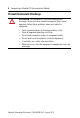
CompactLogix EtherNet/IP Communication Module Prevent Electrostatic Discharge ATTENTION: This equipment is sensitive to electrostatic discharge, which can cause internal damage and affect normal operation. Follow these guidelines when you handle this equipment: • • • • • • Touch a grounded object to discharge potential static. Wear an approved grounding wriststrap. Do not touch connectors or pins on component boards. Do not touch circuit components inside the equipment.
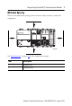
CompactLogix EtherNet/IP Communication Module 7 Minimum Spacing Plan for this minimum spacing from enclosure walls, wireways, and other equipment. 1 2 2 Power OUT L1 L2/N 1 31609-M See Specifications on page 22 for the temperature range. Item Description 1 105 mm (4 in.) 2 90 mm (3.54 in.
CompactLogix EtherNet/IP Communication Module What You Need Item Cat. No.
CompactLogix EtherNet/IP Communication Module 9 If You Are Using Screws to Mount Your Modules IMPORTANT Do not use screws and DIN rail to mount the modules. It is possible to break the mounting tabs off if you screw the modules to the panel while they are on DIN rail. The steps in these instructions show how to mount the modules on DIN rail. If you are using screws instead of DIN rail, make these changes to the instructions. 1.
CompactLogix EtherNet/IP Communication Module Install the DIN Rail Mount the DIN rail in a suitable location. ATTENTION: This product is grounded through the DIN rail to chassis ground. Use zinc plated yellow-chromate steel DIN rail to assure proper grounding. The use of other DIN rail materials (for example, aluminum or plastic) that can corrode, oxidize, or are poor conductors, can result in improper or intermittent grounding. Secure DIN rail to mounting surface approximately every 200 mm (7.8 in.
CompactLogix EtherNet/IP Communication Module 11 Mount the Controller on the DIN Rail 1 31595-M 2 31596 -M Rockwell Automation Publication 1768-IN002B-EN-P - August 2010
CompactLogix EtherNet/IP Communication Module Mount the EtherNet/IP Communication Module on the DIN Rail 1 31597-M 2 b a c Rockwell Automation Publication 1768-IN002B-EN-P - August 2010 31598 -M
CompactLogix EtherNet/IP Communication Module 13 Mount the Power Supply on the DIN Rail 31599-M Rockwell Automation Publication 1768-IN002B-EN-P - August 2010
CompactLogix EtherNet/IP Communication Module Mount the I/O Modules on the DIN Rail a 1 b d c 31600-M b 2 c a 31601-M Rockwell Automation Publication 1768-IN002B-EN-P - August 2010
CompactLogix EtherNet/IP Communication Module 15 Wire the Module Use an RJ45 connector to connect to the EtherNet/IP network. 8 ------ NC 7 ------ NC 6 ------ RD5 ------ NC 4 ------ NC 3 ------ RD+ 2 ------ TD1 ------ TD+ 8 1 Connect the Module IMPORTANT We recommend connecting the module to the network via a 100 MB Ethernet switch, which will reduce collisions and lost packets and increase network bandwidth.
CompactLogix EtherNet/IP Communication Module Attach the RJ45 connector to the Ethernet port on the bottom of the module. 1 31611-M Item Description 1 Ethernet port Configure the Module To configure your module, refer to the configuration chapter of your EtherNet/IP Modules User Manual, publication ENET-UM001.
CompactLogix EtherNet/IP Communication Module 17 Confirm Your Installation 1 2 2 Power OUT L1 L2/N 31608-M Item Description 1 Solid or flashing green 2 Solid green See Troubleshoot the Module on page 20 if the status indicators are in other states.
CompactLogix EtherNet/IP Communication Module Remove a Module 1 c - Off b d f Power OUT L1 L2/N a 31602-M e 2 a c Power OUT L1 L2/N b Rockwell Automation Publication 1768-IN002B-EN-P - August 2010 31607-M
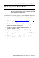
CompactLogix EtherNet/IP Communication Module 19 Why Wait for the Lights to Turn Off Before I Remove a Module? After you turn off the power, wait for all of the lights on the power supply and controller to turn off before you disconnect any modules. IMPORTANT When you turn the CompactLogix power supply off, make sure you wait for all status indicators on the power supply and controller to turn off before disconnecting any part from the system.
CompactLogix EtherNet/IP Communication Module Troubleshoot the Module The three bi-color (red/green) status indicators on the module provide diagnostic information about the module and its connections to the network. If the alphanumeric display and status indicators do not sequence through the expected states, refer to the troubleshooting tables.
CompactLogix EtherNet/IP Communication Module 21 Status Indicators The module status indicators provides the following information. Indicator Status Description NET Off Module is not powered, or does not have an IP address. • Verify there is chassis power and the module is completely inserted into the chassis and backplane. • Make sure the module has been configured. Flashing Green Module has obtained an IP address, but has no established connections.
CompactLogix EtherNet/IP Communication Module Specifications Technical Specifications - 1768-ENBT Attribute 1768-ENBT Backplane current 834 mA at 5.2V DC Power consumption 4.34 W Power dissipation 4.38 W Isolation (continuous-voltage rating) 30V, Functional Insulation Type, Ethernet network to system Type tested at 710V DC for 60 s Wire Size Ethernet network connections: RJ45 connector according to IEC 60603-7, 2 or 4 pair Category 5e minimum cable according to TIA 568-B.
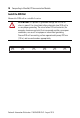
CompactLogix EtherNet/IP Communication Module 23 Environmental Specifications - 1768-ENBT Attribute 1756-ENBT Temperature, operating • IEC 60068-2-1 (Test Ad, Operating Cold) • IEC 60068-2-2 (Test Bd, Operating Dry Heat) • IEC 60068-2-14 (Test Nb, Operating Thermal Shock) 0…60 °C (32...
CompactLogix EtherNet/IP Communication Module Environmental Specifications - 1768-ENBT Attribute 1756-ENBT Surge transient immunity • IEC 61000-4-5 ±2 kV line-earth(CM) on communication ports Conducted RF immunity • IEC 61000-4-6: 10V rms with 1 kHz sine-wave 80%AM from 150 kHz…80 MHz Enclosure type rating None (open-style) Certifications Certification (when product is marked)(1) Value c-UL-us • UL Listed Industrial Control Equipment, certified for US and Canada. See UL File E65584.
CompactLogix EtherNet/IP Communication Module 25 Additional Resources These documents contain additional information concerning related Rockwell Automation products. Resource Description EtherNet/IP Modules in Logix5000 Control Systems User Manual, publication ENET-UM001 Provides information about how to use EtherNet/IP modules with vrious Logix5000 controllers.
CompactLogix EtherNet/IP Communication Module Notes: Rockwell Automation Publication 1768-IN002B-EN-P - August 2010
CompactLogix EtherNet/IP Communication Module 27 Notes: Rockwell Automation Publication 1768-IN002B-EN-P - August 2010
Rockwell Automation Support Rockwell Automation provides technical information on the Web to assist you in using its products. At http://www.rockwellautomation.com/support/, you can find technical manuals, a knowledge base of FAQs, technical and application notes, sample code and links to software service packs, and a MySupport feature that you can customize to make the best use of these tools.