
User Manual Manual


60 Rockwell Automation Publication 1766-UM001H-EN-P - May 2014
Chapter 4 Communication Connections
For more information on MicroLogix 1400 communications, refer to the
MicroLogix 1400 Programmable Controllers Instruction Set Reference Manual,
publication 1766-RM001.
Default Communication
Configuration
The MicroLogix 1400 communication Channel 0 has the following default
communication configuration.
See Chapter 5 for more information about using the LCD Display.
See Appendix E for more information about communicating.
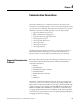
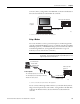
Using the Communications
Toggle Functionality
The Communications Toggle Functionality can be operated using the LCD
display on the controller, as shown below.
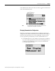
Use the Communications Toggle Functionality to change from the user-defined
communication configuration to the default communications mode and back on
Channel 0. The Default Communications (DCOMM) indicator on the LCD
display operates to show when the controller is in the default communications
TIP
For Channel 0, the default configuration is present when:
• The controller is powered-up for the first time.
• The communications toggle functionality specifies default
communications (specified using the LCD Display. The DCOMM
indicator on the LCD Display is on, that is, lit in solid rectangle).
• An OS upgrade is completed.
DF1 Full-Duplex Default Configuration Parameters
Parameter Default
Baud Rate 19.2 KBps
Parity none
Source ID (Node Address) 1
Control Line no handshaking
Error Detection CRC
Embedded Responses auto detect
Duplicate Packet (Message) Detect enabled
ACK Timeout 50 counts
NAK retries 3 retries
ENQ retries 3 retries
Stop Bits 1
Data Bits 8