
User Manual Manual


40 Rockwell Automation Publication 1766-UM001H-EN-P - May 2014
Chapter 3 Wire Your Controller
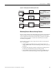
Figure 13 - Analog Output
Analog Channel Wiring Guidelines
Consider the following when wiring your analog channels:
• The analog common (COM) is connected to earth ground inside the
module. These terminals are not electrically isolated from the system. They
are connected to chassis ground.
• Analog channels are not isolated from each other.
• Use Belden 8761, or equivalent, shielded wire.
• Under normal conditions, the drain wire (shield) should be connected to
the metal mounting panel (earth ground). Keep the shield connection to
earth ground as short as possible.
• To ensure optimum accuracy for voltage type inputs, limit overall cable
impedance by keeping all analog cables as short as possible. Locate the I/O
system as close to your voltage type sensors or actuators as possible.
• The controller does not provide loop power for analog inputs. Use a power
supply that matches the transmitter specifications as shown below.
OV1O/3 O/4
O/5
O/7 O/8 O/10
O/6 O/9 O/11
OV0
3
C
DC4
VAC
DC6
VAC
COM
ANA
DC5
VAC
Output Terminal Block
Voltage Load
44680
Voltage Load