
User Manual Manual

282 Rockwell Automation Publication 1766-UM001H-EN-P - May 2014
Appendix F MicroLogix 1400 Distributed Network Protocol (DNP3)
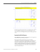
Control Generating Event
The MicroLogix 1400 checks all elements in the Object Data file for changes at
the end of a scan and generates events where needed.
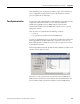
The key method to turn on and off event generating by ladder logic is to assign or
un-assign the Class information bits in the Object Config Files.
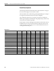
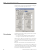
The example below shows how to control the event generation condition by
ladder logic and implements Deadband for Analog Input Objects (which is only
necessary for Series A MicroLogix 1400)
In this example, for 16-bit Analog Input point 0(N11:0), if the absolute value of
the difference between the present value of N11:0 and the value that was most
recently queued as an event for that point exceeds the deadband value, then an
event is generated for that point.
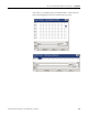
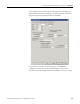
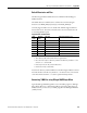
Data File List
Name Number Type Scope Debug Words Elements Last
Output 0 O Global No 18 6 O:5
Input 1 I Global No 24 8 I:7
Status 2 S Global No 0 66 S:65
Binary 3 B Global No 1 1 B3:0
Timer 4 T Global No 3 1 T4:0
Counter 5 C Global No 3 1 C5:0
Control 6 R Global No 3 1 R6:0
Integer 7 N Global No 1 1 N7:0
Float 8 F Global No 2 1 F8:0
16-bit Analog Input Object File 11 N Global No 10 10 N11:9
Binary Output Object File 12 B Global No 10 10 B12:0
16-bit32-bit Analog Input Config File 21 B Global No 10 10 B21:9
A16I OLD 30 N Global No 10 10 N30:9
A16I DEADB 31 N Global No 10 10 N31:9
A16I Temp 32 N Global No 10 10 N32:9