
User Manual Manual


Rockwell Automation Publication 1766-UM001H-EN-P - May 2014 269
MicroLogix 1400 Distributed Network Protocol (DNP3) Appendix F
• File Number
• File Element
• File Sub Element.
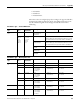
When these values are configured properly according to the supported data files,
the MicroLogix 1400 responds with a g87v1 object filled with the value in the
data file. The following table shows the supported data files for the Point
Addressing.
Point Address Type — Standard DNP3 Point
Point Address
Type
Data Type
Code
Maximum Data
Length (bytes)
Point Type Point Index Low Byte Point Index High Byte
Standard DNP3
Point
NONE = 0 0 NONE = 0:
No point type is
associated.
0
NONE = 0
UINT = 2
INT = 3
OSTR = 5
BSTR = 6
TIME = 7
0
0, 1, 2 or 4
0, 1, 2 or 4
0 to 255
0 to 255
0 or 6
BI = 1: Binary input 0 to Maximum 4095
When the Data Types other than OSTR and BSTR are used, the
Point Index must be set to a point offset that is divisible by 16.
B2I = 3:
Double-bit input
0 to Maximum 2047
When the Data Types other than OSTR and BSTR are used, the
Point Index must be set to a point offset that is divisible by 8.
CI = 20:
Counter
0 to Maximum 511
AI = 30:
Analog input
0 to Maximum 767
BCD = 101:
BCD point
0 to Maximum 255
Point Address Type — MicroLogix Data File
Point Address
Type
Data Type
Code
Maximum Data
Length (bytes)
File Number File Element File Sub-Element
MicroLogix Data
File
NONE = 0 0 0 0 0
VSTR = 1 0…82 9…255 (ST) 9…255 0…40
UINT = 2 0, 1, 2 or 4 2(S)
3, 9…255 (B)
7, 9…255 (N)
9…255 (L)
0…65 for S
0…255 for B, N, L
0 for S, N, L
0…15 for B
INT = 3 0, 1, 2 or 4 2(S)
3, 9…255 (B)
7, 9…255 (N)
9…255 (L)
0…65 for S
0…255 for B, N, L
0 for S, N, L
0…15 for B
FLT = 4 0 or 4 8, 9…255 (F) 0…255 0
OSTR = 5 0…255 2(S)
3, 9…255 (B)
7, 9…255 (N)
0…65 for S
0…255 for B, N,
0 for S, N
0…15 for B
BSTR = 6 0…255 2(S)
3, 9…255 (B)
7, 9…255 (N)
0…65 for S
0…255 for B, N,
0 for S, N
0…15 for B
TIME = 7 0…6 2(S)
3, 9…255 (B)
7, 9…255 (N)
9…255 (L)
0…65 for S
0…255 for B, N, L
0 for S, N, L
0…15 for B