
User Manual Manual


64 Rockwell Automation Publication 1766-UM001H-EN-P - May 2014
Chapter 5 Using the LCD
:
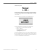
LCD Default Screen – I/O Status Screen
.
This is the default screen of the display, allowing you to monitor controller and
I/O Status. For more information on the I/O Status screen, see I/O Status on
page 67.
Operating Buttons
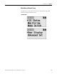
Main Menu Items
Menu Item Description For details, refer to
I/O Status Displays the I/O Status screen, which shows the I/O status of the
embedded digital I/O.
I/O Status on page 67
Monitoring Allows you to view and change the data value of a bit and an
integer file.
Monitor User Defined Target Files on page 69
Monitoring Integer Files on page 74
Mode Switch Allows you to change the mode switch selection. Using the Mode Switch on page 86
User Display Displays the user defined LCD screen Using a User Defined LCD Screen on page 89
Advanced Set Allows you to configure or view the following:
• Change the key in mode for value entry for a trim pot.
• Use the communications toggle functionality.
• View and change the Ethernet network configuration.
• Change the data value of trim pots.
• View system information, such as OS series and firmware
version.
• User communication EEPROM functionality.
• Change LCD contrast and backlight option.
• Modbus RTU Slave Node Address
• Changing Key In Mode on page 92
• Using Communications Toggle Functionality on page 94
• Viewing Ethernet Status on page 94
• Using Trim Pots on page 105
• I/O Status on page 67
• Saving/Loading Communication EEPROM on page 110
• LCD setup on page 113
• See Protocol Configuration on page 116
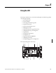
Button Function
Cursor Buttons Move cursor
Select menu item
Choose file numbers, values, etc.
OK Next menu level, store your entry, apply the changes
ESC Previous menu level, cancel your entry
COM
M
0
CO
M
M
1
DCOMM
BAT. L
O
U-
DI
SP
COM
M
2
ESC
OK
44612