Pump Station Controller Quick Start
Important User Information Solid state equipment has operational characteristics differing from those of electromechanical equipment. Safety Guidelines for the Application, Installation and Maintenance of Solid State Controls (publication SGI-1.1 available from your local Rockwell Automation sales office or online at http://www.rockwellautomation.com/literature/) describes some important differences between solid state equipment and hard-wired electromechanical devices.
Table of Contents Table of Contents Preface Introduction . . . . . . . . . . . . . . . . . . . . . . . . . . . . . . . . . . . . . . . . . . . . . . . 3 Chapter 1 Configuration and Operation Pump Station Controller . . . . . . . . . . . . . . . . . . . . . . . . . . . . . . . . . . . . . 5 Chapter 2 Drawing Set 1Publication IASIMP-QS037A-EN-P - May 2013 2013 Pump Station Controller Hardware Drawings . . . . . . . . . . . . . . . . . . .
2 Publication IASIMP-QS037A-EN-P - May 2013 2013
Preface Introduction This Quick Start Guide contains step-by-step instructions for configurating and operating the Pump Station Controller. The Controller consists of a standard pre-engineered package using off-the-shelf products including the MicroLogix 1400 PLC, PanelView Component C600 HMI and PowerFlex drives. Application files are also supplied so no PLC programming is required and HMI screens are pre-programmed.
Preface Notes: 4 Publication IASIMP-QS037A-EN-P - May 2013
Chapter 1 Configuration and Operation Pump Station Controller Introduction This application uses the MicroLogix 1400 and PanelView Component C600 to provide a "stand alone" multifunction pump controller that allows the user the ability to choose between a pump down (lift station), pump up (water tank), or a pressure follower (water distribution) control process, with just a few simple screen selections. Functionality includes: ● Control of up to 4 pumps. ● User assignable inputs.
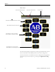
Chapter 1 Main Screen Flashes when a Warning exists Flashes when an Alarm exists Common header Not visible until an application has been selected Only visible if analog device is being used Legend depends on if Pressure Follower” mode is selected or Level mode is selectd Legend depends on if Pressure Follower, Level Pump Down or Level Pump Up mode is selected The main screen displays configuration, monitoring and maintenance controls.
Chapter 1 Configuring the Application The functions available when you select the Application Config button include: ● Select the pumps and pump modes ● Select primary and secondary measuring devices ● Select control devices for all active pumps ● Assign digital inputs and their states ● Assign backup pumps Each of the configuration screens contains standard navigational tools: ● Press Prev or Next to navigate between screens. ● Press Up, Down, or Enter to navigate available choices on a single screen.
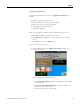
Chapter 1 2. Press Next to proceed to the Measuring Setup screen. From the Measuring Setup screen you can: – Use the Up/Down buttons to select the primary measuring device. TIP If Pressure Follower mode is selected then Analog "In 0" is the only option for the primary measuring device. – Select a secondary measuring device TIP If the primary measuring device is an analog device, you can assign a float to be used as backup (not available if primary measuring is floats).
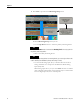
Chapter 1 3. Press Next to proceed to the Motor Control Setup screen. In the example shown, four pumps have been configured; the screen will only display as many pumps as you set up in the initial configuration screen. From the Motor Control Setup screen you can use the Up/Down buttons to select the pump control device.
Chapter 1 As a flow totalizer this can be very accurate. However, using it to calculate flow rate is not as accurate as using analog input I:1.1 as a flow rate input. – Press Enter Gallons Per Pulse to set the appropriate gallons per input pulse 5. Press Next to proceed to the next Digital Inputs Assign screen. From the remaining Digital Inputs Assign screens you can: – Press Normally Open or Normally Closed to set the state to match the way the digital input is wired on the field device.
Chapter 1 Publication IASIMP-QS037A-EN-P - May 2013 NOT USED --(Selection 0 of 31) Pump 2 OL/Fault (Selection 11 of 31) Low Pressure (Selection 22 of 31) Low Level (Selection 1 of 31) Pump 3 OL/Fault (Selection 12 of 31) High Pressure (Selection 23 of 31) Pumps Stop (Selection 2 of 31) Pump 4 OL/Fault (Selection 13 of 31) Power failure (Selection 24 of 31) Lead Start (Selection 3 of 31) Pump 1 Motor Over Temp (Selection 14 of 31) Generator Running (Selection 25 of 31) Lag Start (Selection 4 of
Chapter 1 – Press Next to proceed to the Backup Pump Select screen. TIP The Backup Pump Selection screen is visible only if Float is selected as the backup on the Measuring Setup screen. If during the measuring device setup, floats are selected as secondary (backup) then these buttons will enable or disable the pumps from running in backup mode. Press the Delay Between Pump Starts (Seconds) to enter the delay before the next one starts when more than one backup pump is enabled.
Chapter 1 Because this is a backup operation likely due to a failure, the pumps do not alternate. Setup Examples Example 1: In a pump down application. Floats are being used as backup. On the Pump Sequence Setup screen, the Primary selection for all pumps is set to Alternate, and the Secondary selections are set to Lag1. And on the Backup Pump Selection screen, lead, lag1 and lag2 pumps are all allowed to run as backup. As the level rises and activates the Lead Start float.
Chapter 1 run because the lag1 pumps are not allowed to run due to the selection on the Backup Pump Selection screen --- 60 sec. time delay --- pump 4 (lag2) starts. Configuring Analog Inputs Now that the application has been set up, you can continue through the rest of the configuration. 1. From the Main screen, press Analog Inputs Config to display the configuration screen. This button is not visible unless an analog device is being used (Measurement Setup screen).
Chapter 1 5. Enter a measurement unit type in the Enter Engineering Unit field. For example: Ft, Inch, PSI. 6. Once the scaled values have been entered, the scaled value of the analog input displays in the Analog Input Scaled Value area. 7. The second analog Input (I:1.1) is the same as input I:1.0. If the second analog input is not being used, it does not need to be set up. Configuring Analog Outputs 1. From the Main screen, press Analog Outputs Config to display the configuration screen. 2.
Chapter 1 Setting the Process Configuration 1. From the Main screen, press Process Config to display the setup screen. The number of pumps shown may vary depending on how many pumps are in use. 2. From the setup screen you can: – Use the UP/DOWN buttons to select between Hand, Off and Auto for each configured pump. – Set a Primary selection for each pump. Select from Alternate, Lead, Lag 1 and Lag 2. – Set a Secondary selection for each pump. Select from Lag 1, Lag 2 and Not Used.
Chapter 1 3. Pumping sequence example #3: Pump #2 is set for “Lead”, pump #1 is set for “Lag 1” and pump #3 is set for “Lag2”. When the level requires a pump to run, pump #2 comes on and runs until the level is satisfied. If the level continues to change and requires another pump to run, pump #1 will start. If the level still continues to change and requires another pump, pump #3 will start. The pumps will continue to run until the stop level is satisfied.
Chapter 1 2. Select the interlock from the list, and then use the Add Interlock button to add it to the Current Interlocks or use the Remove Interlock button to remove it from the Current Interlocks. For example: If Pump Seal Fail is in an alarm state, press Remove Interlock to allow the pump to continue running in that alarm state. A white X in a red circle indicates an interlock that has been removed, while a blue check mark in a gray box indicates an interlock that has been added.
Chapter 1 Pressure Setpoints From the first Pressure Setpoints screen you can: – Press Pressure Setpoint to enter the desired system pressure. – Press Start Pressure to set the pressure (combined with the time delay) at which the Lag 1 and Lag 2 pumps will come on if the desired pressure is unable to be maintained. – View the current pressure reading (analog input must have been set up previously).
Chapter 1 – Press VFD # Manual Speed Hz to set the speed at which the drive will run when placed into Manual. – Press Enter The Alternation Time In Minutes to set the time between pump alternations. This is only used if the Primary selection is set to Alternation on the Process Configuration screen. TIP Lead pump alternation will only occur if the lead pump is the only pump running.
Chapter 1 – View pump status, mode and sequence information, as shown below Pump Auto selected Pump run sequence set to Alternate Pump Hand selected Pump run sequence set to Lead Pump Off selected Pump run sequence set to Lag 1 Pump stopped Pump Down Overview Screen From the Pump Down Overview screen you can: – – – – Publication IASIMP-QS037A-EN-P - May 2013 View the 20mA scaled value View the current level scaled value View the 4mA scaled value View pump status, mode and sequence information, as
Chapter 1 Pump Up Overview Screen From the Pump Up Overview screen you can view pump status, mode, sequence and level information. Maintenance Screen From the Maintenance screen you can: – The Secured Settings button is only accessible with "Admin" or "Supervisor" access. – Press VFD # Speed Hz to enter the desired speed for each VFD. The VFD # Speed Hz button is visible only if PowerFlex 4 VFD or Other VFD is selected in the Motor Control Setup screen.
Chapter 1 – Press Pump Statistics to open the Pump Statistics screen. Refer to Pump Statistics Screen on page 23. The Pump Statistics button is only visible after an application has been assigned – Press PID Tuning to access the PD Tuning screen. Refer to PID Tuning Screen on page 24.
Chapter 1 PID Tuning Screen From the PID Tuning screen you can: – Select a pump to view or change the PID values for that pump. The number of pumps visible depend on how many are in use. – Press Enter Prop. Gain (Kc) to enter the gain value for the PID. – Press Enter Integral Reset (Ti) to enter the reset value for the PID. – Press Enter Derivative Rate (Td) to enter the rate value for the PID. – Press Enter Deadband to enter the deadband value for the PID.
Chapter 1 If a PowerFlex 4 series VFD is being used, you can save different sets of parameters under different recipe names. If you save the parameters to an existing database recipe, the previous recipe will be overwritten. To save a recipe: 1. From the PowerFlex 4 VFD Parameters screen, press Save PowerFlex 4 VFD Parameters Into Database to open the Save VFD Parameters screen.. 2.
Chapter 1 – Press CLEAR THE SAVED RECIPE to clear the selected database recipe. 3. Once the desired recipe is selected from the list, press VFD (NODE) # to select the VFD using the parameters you want to save. This option is visible only if a PowerFlex VFD is found at the appropriate node. To load a recipe: 1. From the PowerFlex 4 VFD Parameters screen, press Load PowerFlex 4 VFD Parameters From Database Into VFD to open the Load VFD Parameters screen. 2.
Chapter 1 Warning Screen From the Warning screen you can: – View the current warning message. – Press Push to Acknowledge Warning to scroll through each active warning if multiple warnings exist. TIP Although some of the warnings can be alarms, they are typically settings or setup issues that have conflicts.
Chapter 1 THE "HAND-OFF-AUTO" SELECTORS FOR ALL PUMPS, IS SET TO "OFF" -- PUMP #1 -HAS ITS OVERLOAD TRIPPED/VFD FAULT INTERLOCK ENABLED AN INPUT NEEDS TO BE ASSIGNED TO "OL TRIPPED/VFD FAULT" OR THE INTERLOCK NEEDS TO BE DISABLED --- PRESSURE MODE SELECTED --AND A "STOP PRESSURE" SET POINT IS SET LOWER THEN A "START PRESSURE" SET POINT -- PUMP #1 -HAS ITS OVER TEMP INTERLOCK ENABLED AN INPUT NEEDS TO BE ASSIGNED TO "OVER TEMP" OR THE INTERLOCK NEEDS TO BE DISABLED --- PUMP DOWN MODE SELECTED --THE PUMP
Chapter 1 -- PUMP #3 -HAS ITS SEAL FAIL INTERLOCK ENABLED AN INPUT NEEDS TO BE ASSIGNED TO "SEAL FAIL" OR THE INTERLOCK NEEDS TO BE DISABLED -- PUMP #4 -HAS ITS OVERLOAD TRIPPED/VFD FAULT INTERLOCK ENABLED AN INPUT NEEDS TO BE ASSIGNED TO "OL TRIPPED/VFD FAULT" OR THE INTERLOCK NEEDS TO BE DISABLED -- PUMP #4 -HAS ITS OVER TEMP INTERLOCK ENABLED AN INPUT NEEDS TO BE ASSIGNED TO "OVER TEMP" OR THE INTERLOCK NEEDS TO BE DISABLED -- PUMP #4 -HAS ITS SEAL FAIL INTERLOCK ENABLED AN INPUT NEEDS TO BE ASSIGNED TO
Chapter 1 appear at the top of the list. Alarms remain in the list until the Clear All Alarms button is pushed on the maintenance screen. Because this list contains past alarms (history), use the UP/DOWN and PAGE UP/PAGE DOWN buttons to scroll through the list. From this screen you can also: – Press View Warnings to go to the Warning screen. Refer to Warning Screen on page 27. – Press Alarm Output Config to go to the Alarm Output Configuration screen. Refer to Alarm Output Configuration on page 32.
Chapter 1 VFD Faults (PowerFlex 4 VFDs only) The VFD Faults screen shows faults for each PowerFlex 4 VFD in use (in this example four VFDs are in use). The fault information comes from the PowerFlex 4 VFD via the Modbus communication. Press RESET VFD FAULT or the stop button on the VFD to reset the VFD fault.
Chapter 1 Alarm Output Configuration From the Alarm Output Configuration screen you can: – Press UP/DOWN to select a process-specific alarm from the list – Press Add Alarm or Remove Alarm to enable or disable the selected process-specific alarm The alarms, when enabled, combine to turn on PLC output O:0/9. If the alarm is not enabled, even though it becomes active, it will not turn the PLC output on. – Press MORE to add pump-specific alarms from the Pump # Alarm Output Configuration screen(s).
Chapter 1 add or remove alarms on additional pumps, if any, otherwise, the button will not be visible. The alarm output screens for pumps #2-4 are the same as pump #1. Secured Screen This screen is only accessible with "Admin" or "Supervisor" access. The Clear Alarm History button is used to clear all of the alarms from the alarm history. PowerFlex 4 series VFD set up (must have firmware version 6.0 or higher) If PowerFlex 4 VFD’s are being used, the following parameters need to be set on each VFD. 1.
Chapter 1 7. PowerFlex 4/40 - A106 (comm loss time) = 10 sec., PowerFlex 400 C106 (comm loss time) = 10 sec. The default time of 5 sec. may work satisfactorily, however during parameter saving and loading, the message instructions in the PLC may take longer than usual, and the additional time may alleviate some nuisance communication faults. 8. PowerFlex 4/40 - A107 (comm format) = 0 (RTU 8-N-1), PowerFlex 400 – C102 (comm format) = 0 (RTU 8-N-1) Panel View C600 (2711C-T6T), Firmware version 1.60 1.
Chapter 1 2. Channel settings.
Chapter 1 36 Publication IASIMP-QS037A-EN-P - May 2013
Chapter 1 MicroLogix Memory Module. The Multifunction Pump Control PLC program comes stored on a 1766-MM1 memory module. To load the program from the memory module into the PLC: 1. Use the up/down buttons on the directional keypad to scroll to the Advanced Set option on the LCD display and push OK. Directional keypad 2. Scroll down to Comms EEPROM and push OK. 3. Scroll to Load from MM and push OK. 4. The Run LED will flash on/off. When loading is complete the Run LED will stay off. Push OK.
Chapter 1 PanelView component program load On initial power up, the PanelView main menu displays. 1. Push File Manager. 2. Use the Up/Down buttons to scroll to USB from the Source list. 3. Use the Up/Down buttons to scroll to Internal from the To list. 4. Push Copy to transfer the application from the USB storage into PanelView. The message Operation Succeeded displays. 5. Press OK to clear the pop-up window.
Chapter 1 6. From the Source list select Internal. 7. Once the source is set to Internal, push Set As Startup. The application name displays under Startup Application. 8. Push Run to launch the application. Security The Panelview has three levels of security: User, Supervisor, and Admin.
Chapter 1 PLC Program Files The PLC code is separated into separate program files. Each file contains the logic associated with certain operations. The Main file contains all of the jump to subroutine (JSR) instructions that scans all of the other files (3-20) sequentially. Recipe Files The parameters for the PowerFlex 4 series VFDs are saved/recalled into/from RCP files. Because a RCP file has a max. file length of 32, there are 7 files required to hold all of the parameters.
Chapter 2 Drawing Set Pump Station Controller Hardware Drawings The Pump Station Controller includes the following drawings: ● Title Page and Sheet Index ● Communications Diagram ● Panel Layout Diagram ● Power Layout Sheets ● Panel I/O Layout Sheets Title Page and Sheet Index Pump Station Title Page and Sheet Index 41Publication IASIMP-QS037A-EN-P - May 2013 Number Title Description Index Title Page and Sheet Index This is the Table of Contents/Cover Sheet for the drawing package.
Chapter 2 Communications Diagram Pump Station Controller Communications Diagram 42 Number Title Description 1 Pump Control Communications Diagram Overview with network connections.
Chapter 2 Panel Layout Diagram Pump Station Controller Panel Layout Diagram Number Title Description 2 Pump Station Controller Panel Layout Diagram You can modify this as needed for your application requirements.
Chapter 2 44 Publication IASIMP-QS037A-EN-P - May 2013
Chapter 2 Publication IASIMP-QS037A-EN-P - May 2013 Number Title Description 3-7 Power Layout Sheets Pump Control Power Distribution, 460VAC Power. 277 VAC Power, and 24VDC Power Drawings.
Chapter 2 Panel I/O Layout Sheets Pump Station Controller Panel I/O Layout Sheets 46 Publication IASIMP-QS037A-EN-P - May 2013
Chapter 2 Publication IASIMP-QS037A-EN-P - May 2013 47
Chapter 2 48 Number Title Description 8-13 Panel I/O Layout Sheet s Pump Control Drive and PLC I/O Drawings.
Rockwell Automation Support Rockwell Automation provides technical information on the Web to assist you in using its products. At http://www.rockwellautomation.com/support/, you can find technical manuals, a knowledge base of FAQs, technical and application notes, sample code and links to software service packs, and a MySupport feature that you can customize to make the best use of these tools.