Installation Instructions MicroLogix™ 1500 Programmable Controller Base Units (Catalog Numbers 1764-24AWA, 1764-24BWA, and 1764-28BXB) http://literature.rockwellautomation.com/idc/groups/literature/documents/in/1 764-in001_-mu-p.pdf FR Cette publication est disponible en français sous forme électronique (fichier PDF). Pour la télécharger, rendez-vous sur la page Internet indiquée ci-dessus. IT Questa pubblicazione è disponibile in Italiano in formato PDF.
MicroLogix™ 1500 Programmable Controller Base Units Publication 1764-IN001B-EN-P - March 2008
Installation Instructions MicroLogix™ 1500 Programmable Controller Base Units (Catalog Numbers 1764-24AWA, 1764-24BWA, and 1764-28BXB) Inside... For More Information.............................................................................. 4 Overview ................................................................................................. 5 Base Unit Description ............................................................................. 6 Hazardous Location Considerations ...................
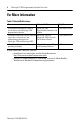
MicroLogix™ 1500 Programmable Controller Base Units For More Information Table 1 Related Publications For Refer to this Document Pub. No. A more detailed description of how to install and use your MicroLogix 1500 programmable controller.
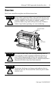
MicroLogix™ 1500 Programmable Controller Base Units 5 Overview Install your controller using these installation instructions. ATTENTION ! Do not remove protective debris strips until after the base and all other equipment in the panel near the base is mounted and wiring is complete. Once wiring is complete, remove protective debris strips and install processor unit. Failure to remove strips before operating can cause overheating.
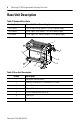
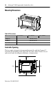
MicroLogix™ 1500 Programmable Controller Base Units Base Unit Description Table 2 Standard Base Units Catalog Number Base Unit I/O and Power Supply 1764-24AWA 120V ac inputs/ relay outputs/ 120/240V ac power supply 1764-24BWA 24V dc inputs/ relay outputs/ 120/240V ac power supply 1764-28BXB 24V dc inputs/ FET and relay outputs/ 24V dc power supply 1 2 7 3 6 1 4 5 Table 3 Base Unit Description Feature Description 1 Removable Terminal Blocks 2 Interface to Expansion I/O, Removable ESD St
MicroLogix™ 1500 Programmable Controller Base Units 7 Hazardous Location Considerations This equipment is suitable for use in Class I, Division 2, Groups A, B, C, D or non-hazardous locations only. The following WARNING statement applies to use in hazardous locations. WARNING ! EXPLOSION HAZARD • Substitution of components may impair suitability for Class I, Division 2. • Do not replace components or disconnect equipment unless power has been switched off or the area is known to be non-hazardous.
MicroLogix™ 1500 Programmable Controller Base Units Environnements dangereux Cet équipement est conçu pour être utilisé dans des environnements de Classe 1, Division 2, Groupes A, B, C, D ou non dangereux. La mise en garde suivante s’applique à une utilisation dans des environnements dangereux. MISE EN GARDE DANGER D’EXPLOSION • La substitution de composants peut rendre cet équipement impropre à une utilisation en environnement de Classe 1, Division 2.
MicroLogix™ 1500 Programmable Controller Base Units 9 Mounting the Controller General Considerations Most applications require installation in an industrial enclosure (Pollution Degree 2) to reduce the effects of electrical interference (Over Voltage Category II) and environmental exposure. Locate your controller as far as possible from power lines, load lines, and other sources of electrical noise such as hard-contact switches, relays, and AC motor drives.
MicroLogix™ 1500 Programmable Controller Base Units Mounting Dimensions A B C Table 6 Dimensions Dimension 1764-24AWA 1764-24BWA Height (A) 138 mm (5.43 in.) Width (B) 168 mm (6.62 in.) Depth (C) 87 mm (3.43 in.) 1764-28BXB Controller Spacing The base unit is designed to be mounted horizontally, with the Compact™ expansion I/O extending to the right of the base unit. Allow 50 mm (2 in.) of space on all sides for adequate ventilation, as shown below.
MicroLogix™ 1500 Programmable Controller Base Units 11 Using a DIN Rail The base unit and expansion I/O DIN rail latches lock in the open position so that an entire system can be easily attached to or removed from the DIN rail. The maximum extension of the latch is 15 mm (0.67 in.) in the open position. A flat-blade screw driver is required for removal of the base unit. The base can be mounted to EN50022-35x7.5 or EN50022-35x15 DIN rails. DIN rail mounting dimensions are shown below.
MicroLogix™ 1500 Programmable Controller Base Units To remove your base unit from the DIN rail: 1. Place a flat-blade screwdriver in the DIN rail latch at the bottom of the base unit. 2. Holding the base unit, pry downward on the latch until the latch locks in the open position. This releases the base unit from the DIN rail. Using Mounting Screws Mount to panel using #8 or M4 screws.
MicroLogix™ 1500 Programmable Controller Base Units 13 To install your base unit using mounting screws: 1. Remove the mounting template from the inside back cover of this document. 2. Secure the template to the mounting surface. (Make sure your base unit is spaced properly, see “Controller Spacing” on page 10). 3. Drill holes through the template. 4. Remove the mounting template. 5. Mount the base unit. 6.
MicroLogix™ 1500 Programmable Controller Base Units Wire Requirements Table 8 Wire Type Recommendation Wire Type Wire Size (2 wire maximum per terminal screw) Solid Cu-90°C (194°F) #14 to #22 AWG Stranded Cu-90°C (194°F) #14 to #22 AWG Wiring torque = 1.13 Nm (10 in-lb) rated; 1.3 Nm (12 in-lb) maximum ATTENTION ! Be careful when stripping wires. Wire fragments that fall into the controller could cause damage.
MicroLogix™ 1500 Programmable Controller Base Units 15 Spade Lug Recommendation The diameter of the terminal screw head is 5.5 mm (0.220 in.). The input and output terminals of the MicroLogix 1500 base unit are designed for the following spade lugs. The terminals will accept a 6.35mm (0.25 in.) wide spade (standard for #6 screw for up to 14 AWG) or a 4 mm (metric #4) fork terminal.
MicroLogix™ 1500 Programmable Controller Base Units Grounding the Controller ATTENTION ! All devices connected to the RS-232 channel must be referenced to base unit ground or floating. Failure to follow this procedure may result in property damage or personal injury. In solid-state control systems, grounding and wire routing helps limit the effects of noise due to electromagnetic interference (EMI).
MicroLogix™ 1500 Programmable Controller Base Units 17 Specifications Table 9 General Specifications Description 1764-24BWA 1764-24AWA 1764-28BXB Number of I/O 12 inputs 12 outputs 12 inputs 12 outputs 16 inputs 12 outputs Line Power 85/265V ac 85/265V ac 20.4 to 30V dc Power Supply Inrush 120V ac = 25A for 8 ms 120V ac = 25A for 8 ms 24V dc = 4A for 150 ms 240V ac = 40A for 4 ms 240V ac = 40A for 4 ms User Power Output 24V dc at 400 mA, 400 µf max.
MicroLogix™ 1500 Programmable Controller Base Units Table 10 Input Specifications Description 1764-24AWA On State Voltage Range 79 to 132V ac Off State Voltage Range Operating Frequency 1764-24BWA and 1764-28BXB Inputs 0 thru 7 Inputs 8 and Higher 14 to 30.0 V dc at 30°C 10 to 30.0 V dc at 30°C (86°F) (86°F) 14 to 26.4 V dc at 55°C 10 to 26.4 V dc at 55°C (131°F) (131°F) 0 to 5V dc 0 to 20V ac 47 Hz to 63 Hz 0 Hz to 20 KHz (1764-24BWA) 0 Hz to 1 KHz(1) (1764-24BWA) • 5.0 mA at 79V ac • 12.
MicroLogix™ 1500 Programmable Controller Base Units 19 Table 13 1764-28BXB FET Output Specifications Specification User Supply Voltage On-State Voltage Drop Current Rating per Point General Operation High Speed Operation(1) (Outputs 2 thru 7) (Outputs 2 and 3 Only) minimum 20.4V dc 20.4V dc maximum 26.4V dc 26.4V dc at maximum load current 1V dc Not Applicable at maximum surge current 2.5V dc Not Applicable maximum load 1A at 55°C (131°F) 100 mA 1.5A at 30°C (86°F) minimum load 1.
MicroLogix™ 1500 Programmable Controller Base Units Table 14 Working Voltage Specification 1764-L24AWA Power Supply Input to Backplane Isolation Verified by one of the following dielectric tests: 1836V ac for 1 second or 2596V dc for 1 second 265V Working Voltage (IEC Class 2 reinforced insulation) Input Group to Backplane Isolation and Input Group to Input Group Isolation Verified by one of the following dielectric tests: 151V ac for 1 second or 2145V dc for 1 second 132V Working Voltage (IEC Cla
MicroLogix™ 1500 Programmable Controller Base Units 21 Table 14 Working Voltage Specification 1764-28BXB Input Group to Backplane Isolation and Input Group to Input Group Isolation Verified by one of the following dielectric tests: 1200V ac for 1 second or 1697V dc for 1 second 75V dc Working Voltage (IEC Class 2 reinforced insulation) FET Output Group to Backplane Isolation and FET Outputs Group to Group Verified by one of the following dielectric tests: 1200V ac for 1 second or 1697V dc for 1 secon
MicroLogix™ 1500 Programmable Controller Base Units Notes: Publication 1764-IN001B-EN-P
MicroLogix™ 1500 Programmable Controller Base Units 23 Notes: Publication 1764-IN001B-EN-P
MicroLogix™ 1500 Programmable Controller Base Units Notes: Publication 1764-IN001B-EN-P
MicroLogix™ 1500 Programmable Controller Base Units 25 Notes: Publication 1764-IN001B-EN-P
Mounting Template 168 mm 35 mm (6.62 in.) (1.37 in.) DIN rail center line. Base Unit Expansion I/O Ligne médiane du rail DIN. Unité de base d'extension d'E/S Mittellinie der DIN-Schiene. Grundeinheiten Línea central del riel DIN. Unità di base E/AErweiterungsmodule Linea centrale della guida DIN Unidad Base l’espansione dei moduli I/O linha de centro do trilho DIN. Unidades Base de expansión de E/S de expansão de E/S 132 mm 122 mm (5.19 in.) (4.813 in.) 147 mm 38 mm (5.78 in.) (1.
Rockwell Automation Support Rockwell Automation provides technical information on the Web to assist you in using its products. At http://support.rockwellautomation.com, you can find technical manuals, a knowledge base of FAQs, technical and application notes, sample code and links to software service packs, and a MySupport feature that you can customize to make the best use of these tools.