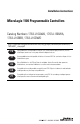
Installation Instructions MicroLogix 1100 Programmable Controllers Catalog Numbers 1763-L16AWA, 1763-L16BWA, 1763-L16BBB, 1763-L16DWD http://literature.rockwellautomation.com/idc/groups/literature/documents/in/1 763-in001_-mu-p.pdf FR Cette publication est disponible en français sous forme électronique (fichier PDF). Pour la télécharger, rendez-vous sur la page Internet indiquée ci-dessus. IT Questa pubblicazione è disponibile in Italiano in formato PDF.
Installation Instructions MicroLogix 1100 Programmable Controllers Catalog Numbers 1763-L16AWA, 1763-L16BWA, 1763-L16BBB, 1763-L16DWD Topic Page Important User Information 4 Additional Resources 5 Overview 6 Controller Description 7 Hazardous Location Considerations 8 Mounting the Controller 9 Connecting 1762 I/O Expansion Modules 15 Wiring the Controller 16 Specifications 22
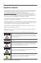
Important User Information Solid state equipment has operational characteristics differing from those of electromechanical equipment. Safety Guidelines for the Application, Installation and Maintenance of Solid State Controls (Publication SGI-1.1 available from your local Rockwell Automation sales office or online at http://literature.rockwellautomation.com) describes some important differences between solid state equipment and hard-wired electromechanical devices.
Additional Resources Resource Description MicroLogix 1100 Programmable Controllers User Manual 1763-UM001 A more detailed description of how to install and use your MicroLogix 1100 programmable controller and expansion I/O system. MicroLogix 1100 Instruction Set Reference Manual1763-RM001 A reference manual that contains data and function files, instruction set, and troubleshooting information for MicroLogix 1100.
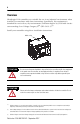
Overview MicroLogix 1100 controllers are suitable for use in an industrial environment when installed in accordance with these instructions. Specifically, this equipment is intended for use in clean, dry environments (Pollution degree 2(1)) and with circuits not exceeding Over Voltage Category II(2) (IEC 60664-1).(3) Install your controller using these installation instructions.
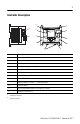
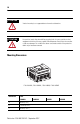
Controller Description 6 5 8 4 12 11 7 ESC OK 3 9 2 10 Item Description 1 Output Terminal Block 2 Battery Connector 3 Bus Connector Interface to Expansion I/O 4 Battery 5 Input Terminal Block 6 LCD Display 7 LCD Display Keypad (ESC, OK, Up, Down, Left, Right) 8 Status LEDs 9 Memory Module Port Cover(1) -or- Memory Module(2) 10 DIN Rail Latches 11 RS-232/485 Communication Port (Channel 0, isolated) 12 Ethernet Port (Channel 1) (1) Shipped with controller.
Catalog Number Description Input Power Digital Inputs Analog Inputs Digital Outputs Comm. Ports 1763-L16AWA 120/240V ac (10) 120V ac (2) voltage input (6) relay 0...10V dc All individually isolated (1) RS-232/485 combo (isolated) (1) Ethernet (2) voltage input (6) relay 24V dc(1) 0 ...10V dc All individually isolated (6) 24V dc (2) voltage input 1763-L16BWA 120/240V ac (6) 24V dc (4) high-speed 1763-L16BBB 24V dc 24V dc(1) 0...
Use only the following communication cables in Class I, Division 2 hazardous locations.
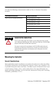
ATTENTION Vertical mounting is not supported due to thermal considerations. ATTENTION Be careful of metal chips when drilling mounting holes for your controller or other equipment within the enclosure or panel. Drilled fragments that fall into the controller could cause damage. Do not drill holes above a mounted controller if the protective debris strips have been removed. Mounting Dimensions C A B 1763-L16AWA, 1763-L16BWA, 1763-L16BBB, 1763-L16DWD Dimension 1763L16AWA A 90 mm (3.5 in.
Controller Spacing The controller mounts horizontally, with the expansion I/O extending to the right of the controller. Allow 50 mm (2 in.) of space on all but the right side for adequate ventilation, as shown below. Top Side ESC OK Bottom DIN Rail Mounting The maximum extension of the latch is 14 mm (0.55 in.) in the open position. A flat-blade screwdriver is required for removal of the controller. The controller can be mounted to EN50022-35x7.5 or EN50022-35x15 DIN rails.
Follow these steps to install your controller on the DIN rail. 1. Mount your DIN rail. (Make sure that the placement of the controller on the DIN rail meets the recommended spacing requirements. See Controller Spacing on page 11. Refer to the mounting template inside the back cover of this document.) 2. If it is open, close the DIN latch. 3. Hook the top slot over the DIN rail. 4. While pressing the controller down against the top of the rail, snap the bottom of the controller into position. 5.
Panel Mounting Mount to panel using #8 or M4 screws. Follow these steps to install your controller using mounting screws. 1. Remove the mounting template from inside the back cover of this document. 2. Secure the template to the mounting surface. (Make sure your controller is spaced properly. See Controller Spacing on page 11.) 3. Drill holes through the template. 4. Remove the mounting template. Mounting Template 5. Mount the controller. 6.
Follow these steps to connect the replaceable battery. 1. Insert the replaceable battery wire connector into the battery connector. 2. Secure the battery connector wires along the wire guide as shown below.
Connecting 1762 I/O Expansion Modules ATTENTION Remove power to the system before installing or removing expansion I/O or damage to the controller may result. Connect 1762 I/O after mounting the controller. 1. Remove the expansion port cover to install expansion I/O modules. 2. Plug the ribbon cable connector into the bus connector. 3. Replace the cover as shown below. The MicroLogix 1100 controller is designed to support up to any four 1762 expansion I/O modules.
Wiring the Controller Terminal Block Layouts The shading in the following terminal block illustrations indicates which terminals are tied to which commons.
1763-L16DWD NOT USED NOT USED + 12/24V DC IN Input Terminal Block DC COM I/0 I/1 I/2 I/3 NOT USED VAC VDC O/0 VAC VDC DC COM O/1 I/4 I/5 I/6 I/7 I/8 I/9 VAC VDC O/2 VAC VDC O/3 VAC VDC O/4 IA COM VAC VDC IV1(+) O/5 IV2(+) NOT USED Output Terminal Block Wire Requirements Wire Type Wire Size (2 wire maximum per terminal) 1 wire per terminal 2 wire per terminal Solid Cu-90 °C (194 °F) 12...20 AWG 16...20 AWG Stranded Cu-90 °C (194 °F) 14...20 AWG 18...
2. Insert it into an open clamp. 3. Using a small, flat-blade screwdriver, tighten the terminal screw. To ensure that the wire conductor is secured inside the clamp, tighten it to the rated torque, 0.56 Nm (5.0 in-lb). The diameter of the terminal screw head is 5.5 mm (0.220 in.). Screw-cage clamp terminal block Surge Suppression ATTENTION Inductive load devices such as motor starters and solenoids require the use of some type of surge suppression to protect the controller output.
Grounding the Controller In solid-state control systems, grounding and wire routing helps limit the effects of noise due to electromagnetic interference (EMI). Run the ground connection from the ground screw of the controller to the ground bus prior to connecting any devices. Use AWG #14 wire. For ac-powered controllers, this connection must be made for safety purposes.
Wiring Your Analog Channels Analog input circuits can monitor voltage signals and convert them to serial digital data. Sensor 2 (V) Voltage Sensor 1 (V) Voltage IA COM IV1(+) IV2(+) The controller does not provide loop power for analog inputs. Use a power supply that matches the transmitter specifications as shown below.
Several specific steps can be taken to help reduce the effects of environmental noise on analog signals: • install the MicroLogix 1100 system in a properly rated (NEMA) enclosure. Make sure that the MicroLogix 1100 system is properly grounded. • use Belden cable #8761 for wiring the analog channels, making sure that the drain wire and foil shield are properly earth grounded. • route the Belden cable separately from any ac wiring.
Specifications General Specifications Description 1763- Dimensions Height: 90 mm (3.5 in.), 104 mm (4.09 in.) (with DIN latch open) Width: 110 mm (4.33 in.), Depth: 87 mm (3.43 in.) Shipping Weight 0.9 kg (2.0 lbs) Number of I/O 12 inputs (10 digital and 2 analog) and 6 outputs Power Supply Voltage 100...240V ac (-15%, +10%) at 47...63 Hz Heat Dissipation Refer to the MicroLogix 1100 Programmable Controllers User Manual, Publication 1763-UM001.
General Specifications Description 1763L16AWA L16BWA L16BBB L16DWD Terminal Screw Torque 0.56 Nm (5.
Input Specifications Digital Inputs Description On-State Voltage Range 1763-L16AWA 79 ...132V ac 1763-L16BWA, -L16BBB Inputs 0 through 3 (4 high-speed dc inputs) Inputs 4 and higher (6 standard dc inputs) 14...24V dc 10...24V dc (14...26.4V dc (+10%) at 65 °C/149 °F) (14...30V dc (+25%) at 30 °C/86 °F) (10...26.4V dc (+10%) at 65 °C/149 °F) (10...30V dc (+25%) at 30 °C/86 °F) Off-State Voltage Range 0...20V ac 0...5V dc Operating Frequency 47...63 Hz 0 Hz...20 kHz 0 Hz...
Digital Input Specifications for 1763-L16DWD Description 1763-L16DWD Inputs 0 through 3 (4 high-speed dc inputs) On-State Voltage Range 10...24V dc at 65 °C/149 °F) (10...30V dc at 30 °C/86 °F) Off-State Voltage Range 0...5V dc Operating Frequency 0 Hz...40 kHz(1) Inputs 4 and higher (6 standard dc inputs) 0 Hz...1 kHz On-State Current: • minimum • 2.0 mA at 10V dc • nominal • 8.5 mA at 24V dc • maximum • 12.0 mA at 30V dc Off-State Leakage Current 1.5 mA max. Nominal Impedance 2.
Output Specifications For Hazardous Locations Applications (Class I, Division 2, Groups A, B, C, D) General Description 1763 -L16AWA, -L16BWA, -L16DWD -L16BBB 1080 VA 360 VA Current per Group Common 3A 3A Current per Controller at 150V max 18 A or total of per-point loads, whichever is less at 240V max 18 A or total of per-point loads, whichever is less Relay and FET Outputs Maximum Controlled Load Maximum Continuous Current: Relay Outputs Turn On Time/Turn Off Time 10 msec (maximum)(1)
Output Specifications For Ordinary (Non-Hazardous) Locations only General Description 1763 -L16AWA, -L16BWA, -L16DWD -L16BBB 1440 VA 720 VA Current per Group Common 5A 5A Current per Controller at 150V max 30 A or total of per-point loads, whichever is less at 240V max 20 A or total of per-point loads, whichever is less Relay and FET Outputs Maximum Controlled Load Maximum Continuous Current: Relay Outputs Turn On Time/Turn Off Time 10 msec (maximum)(1) Load Current 10 mA (minimum) (1)
BBB FET Output Specifications Description General Operationl Power Supply Voltage 24V dc (-15%, +10%) High Speed Operation(1) (Output 2 and 3 Only) On-State Voltage Drop: • at maximum load current • 1V dc • Not Applicable • at maximum surge current • 2.5V dc • Not Applicable • maximum load • See graphs below • 100 mA • minimum load • 1.0 mA • 10 mA • maximum leakage • 1.0 mA • 1.
BBB FET Output Specifications Description General Operationl High Speed Operation(1) (Output 2 and 3 Only) Turn-On Time (maximum) 0.1 ms 6 µs Turn-Off Time (maximum) 1.0 ms 18 µs Repeatability (maximum) Not Applicable 2 µs Drift (maximum) Not Applicable 1 µs per 5 °C (9 °F) (1) Output 2 and 3 are designed to provide increased functionality over the other FET outputs.
Working Voltage (1763-L16BWA) Description 1763-L16BWA Power Supply Input to Backplane Isolation Verified by one of the following dielectric tests:1836V ac for 1 second or 2596V dc for 1 second 265V ac Working Voltage (IEC Class 2 reinforced insulation) Input Group to Backplane Isolation and Input Group to Input Group Isolation Verified by one of the following dielectric tests: 1100V ac for 1 second or 1697V dc for 1 second Output Group to Backplane Isolation Verified by one of the following diele
Working Voltage (1763-L16DWD) Description 1763-L16DWD Input Group to Backplane Isolation and Input Group to Input Group Isolation Verified by one of the following dielectric tests: 1200V ac for 1 second or 1697V dc for 1 second Output Group to Backplane Isolation Verified by one of the following dielectric tests: 1836V ac for 1 second or 2596V dc for 1 second 75V dc Working Voltage (IEC Class 2 reinforced insulation) 265V ac Working Voltage (IEC Class 2 reinforced insulation).
Notes:
95.00 mm (3.740 in.) 4.6 mm (0.181 in.) DIN rail center line. Ligne médiane du rail DIN. Mittellinie der DIN-Schiene. Línea central del riel DIN. Linea centrale della guida DIN. linha de centro do trilho DIN. Expansion I/O d'extension d'E/S E/A Erweiterungsmodule l'espansione dei moduli I/O 100.00 mm (3.937 in.
IP: IP: S/MASK: S/MASK: G/WAY: G/WAY: INPUTS OUTPUTS INPUTS OUTPUTS 0 0 1 1 0 2 0 2 1 3 1 3 2 4 2 4 3 5 3 5 4 6 4 6 5 7 5 7 6 8 6 8 7 9 7 9 8 10 8 10 9 11 9 11 10 10 11 11
Rockwell Automation Support Rockwell Automation provides technical information on the Web to assist you in using its products. At http://support.rockwellautomation.com, you can find technical manuals, a knowledge base of FAQs, technical and application notes, sample code and links to software service packs, and a MySupport feature that you can customize to make the best use of these tools.