User Manual MicroLogix 1100 Embedded Web Server Bulletin 1763 Controllers
Important User Information Solid-state equipment has operational characteristics differing from those of electromechanical equipment. Safety Guidelines for the Application, Installation and Maintenance of Solid State Controls (publication SGI-1.1 available from your local Rockwell Automation sales office or online at http://www.rockwellautomation.com/literature/) describes some important differences between solid-state equipment and hard-wired electromechanical devices.
Summary of Changes The information below summarizes the changes to this manual since the last printing. To help you find new and updated information in this release of the manual, we have included change bars as shown next to this paragraph. The table below lists the sections that document new features and additional or updated information about existing features. Web view disable function is added. Topic Page Disable Web View 9 Browser support is specified as Internet Explorer 6.0 , 7.0, and 8.0.
Chapter 1 Notes: iv Rockwell Automation Publication 1763-UM002D-EN-P - May 2014
Table of Contents Chapter 1 MicroLogix 1100 Embedded Web Server How to Use This Chapter . . . . . . . . . . . . . . . . . . . . . . . . . . . . . . . . . . . . . . . . . . 1 Typical Applications . . . . . . . . . . . . . . . . . . . . . . . . . . . . . . . . . . . . . . . . . . . . . . . 1 Browser Requirements. . . . . . . . . . . . . . . . . . . . . . . . . . . . . . . . . . . . . . . . . . . . . . 1 Connect the MicroLogix 1100 controller to the Network . . . . . . . . . . . . . 2 1.
Table of Contents Notes: vi Rockwell Automation Publication 1763-UM002D-EN-P - May 2014
Chapter 1 MicroLogix 1100 Embedded Web Server How to Use This Chapter Rockwell Automation offers enhanced MicroLogix 1100 controllers for your EtherNet/IP control systems so you can monitor data remotely via web pages. This chapter shows how you can use a MicroLogix 1100 controller in your control system.
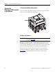
Chapter 1 MicroLogix 1100 Embedded Web Server 1. Connect the module to the network Connect the MicroLogix 1100 controller Connect the MicroLogix 1100 controller to the Ethernet network. The RJ-45 to the Network connector is on the left-hand side of the module. 2. Obtain an IP address. IMPORTANT For more information, see MicroLogix1100 Programmable Controllers User Manual, 1763-UM001. By default, the MicroLogix 1100 controller is BOOTP enabled.
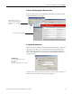
MicroLogix 1100 Embedded Web Server Chapter 1 3. Access the home page of the web server. From your web browser, enter the IP address of the MicroLogix 1100 controller. The module displays its Home page Specify the IP address of the MicroLogix 1100 controller in the Address window of your web browser. This is the module’s Home page. 4. Log into the web server. Many of the features of the MicroLogix 1100 controller require you to log in with appropriate access.
Chapter 1 MicroLogix 1100 Embedded Web Server Navigate the MicroLogix 1100 Controller You navigate the web server’s web pages by using the navigation panel on the left of the screen. There are also tabs across the top you can use to navigate the sections within folders. Tabs across the top match the documents within a folder, as shown in the left navigation panel. Click folders to open and close additional levels of information. Click a document to display a web page showing specific information.
Chapter 2 Use Data Views to Access Controller Data How to Use This Chapter The MicroLogix 1100 controllers provide access to the controller data table files. This chapter shows you how to set up data views of data table files. Topic Overview of Data Views Page Overview of Data Views 5 Change an Access Group 6 Monitor Data Views and Data Table File 7 Change Data Table Files 7 Disable Web View 9 Data views give you the ability to read from controller through a browser interface.
Chapter 2 Use Data Views to Access Controller Data Change an Access Group Each data view contains a group of files that you want to monitor. Each MicroLogix 1100 controller can support multiple data views. One browser supports one data view, so if you want to look at many data views, you need to run a corresponding number of browsers. You change an access group from the Data Views → New Data View page. 1.
Use Data Views to Access Controller Data Chapter 2 Monitor Data Views and Data Table File Use the Data Views → Data Views page to view existing data table files. Click the file name to view the data within a data table file. Data View Page The Data Views page displays a list of the data table files, their type, and size in elements for a connected MicroLogix 1100, as shown in the following example. Each file contains a hyperlink that takes you to the specific Data Views page for that file.
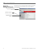
Chapter 2 Use Data Views to Access Controller Data Administrator access level can change the Data Table Files. When you click N7 in Data Views, Data Writable appears beside a Data File Type (Integer here) as shown below. How to Change a Data File Type The following steps assume Binary type is used. 1. Change Display As to Binary, then the following screen appears. 2. Double-click the data you want to change, then the background color becomes pink.
Use Data Views to Access Controller Data Chapter 2 3. Enter a value and either press Enter or click somewhere in the screen, then a confirmation window appears. 4. Click OK to change the value in the server. If following screen appears when the value is successfully saved into the server. If the following screen appears, the value is not saved and the value returns to the original value.
Chapter 2 Use Data Views to Access Controller Data and checking the Web View Disable checkbox as shown below. Any data file property changes must be made offline and downloaded to the processor.
Chapter 3 Manage User Accounts and Access Levels How to Use This Chapter This chapter describes how to configure user access levels to different information on the module. Page Topic User Accounts and Privilege Classes 11 Configure Access Limits for Web Pages 12 Create User Accounts 13 Recover with Unknown Password 14 By assigning user accounts with different access levels, you can manage which users have access to view network configuration or have access to view and change data views.
Chapter 3 Manage User Accounts and Access Levels Configure Access Limits for Web Pages Each page in the MicroLogix 1100 controller has one of these protection levels: • Administrator • Write • Read The protection levels are hierarchical. Administrator users can access Read protected pages. These predefined pages (those web pages that come with the MicroLogix 1100 controller) in the MicroLogix 1100 controller have these default access levels.
Manage User Accounts and Access Levels Chapter 3 Create User Accounts You need Administrator access to create and modify user accounts. You can create as many as 10 individual accounts. You manage accounts from the Administrative Settings → User Management → Edit Users page. In this field Do this User ID Enter the user name for the account.
Chapter 3 Manage User Accounts and Access Levels Recover with Unknown Password 14 Update the firmware using ControlFlash to initialize both user accounts and the access level of data view. This feature is supported only when the OS FRN is 3 (HTML File Revision is 1.2) or later.
Chapter 4 Monitor Diagnostics How to Use This Chapter This chapter describes the diagnostics presented on the user-oriented diagnostic pages. Page Topic MicroLogix 1100 Controller Diagnostics MicroLogix 1100 Controller Diagnostics 15 Diagnostic Overview 16 Network Settings 17 Network Status 18 The MicroLogix 1100 controller provides four diagnostic pages of user-oriented diagnostics.
Chapter 4 Monitor Diagnostics Diagnostic Overview This field The Diagnostics → Diagnostic Overview page presents a summary of the current configuration and overall status of the MicroLogix 1100 controller. This summary includes: • Ethernet configuration. • Ethernet connection use.
Monitor Diagnostics Chapter 4 Network Settings The Diagnostics → Network Settings page presents a summary of the current Ethernet configuration for MicroLogix 1100. This summary includes: • Ethernet address details. Any fields not configured remain blank.
Chapter 4 Monitor Diagnostics Network Status This field The Diagnostics → Network Status page presents a summary of the status of communication activity on the Ethernet network. This summary includes: • Ethernet network configuration. • packets sent and received over the Ethernet network. • frames sent and received over the Ethernet network.
Monitor Diagnostics Chapter 4 This field Specifies Carrier Sense Errors Times that the carrier sense condition was lost or never asserted when attempting to transmit a frame MAC Receive Errors Frames for which reception on the Ethernet interface failed due to an internal MAC sublayer receive error CRC Errors Frames for which CRC error is detected Rockwell Automation Publication 1763-UM002D-EN-P - May 2014 19
Chapter 4 Monitor Diagnostics Notes: 20 Rockwell Automation Publication 1763-UM002D-EN-P - May 2014
Index A access group creating 2-8 access levels classes 3-15 access limits configuring 3-16 accessing typical application 1-3 Administrator access 3-16 authentication 3-15 B browser requirements 1-3 C configuring access limits 3-16 user accounts 3-17 connecting 1-4 creating access group 2-8 D data views monitoring 2-9 overview 2-7 Diagnostic Overview 4-20 diagnostics diagnostic overview 4-20 Ethernet statistics 4-22 network settings 4-21 I installing 1-4 IP address 1-4 M MicroLogix 1100 Controller Dia
22 Notes: Publication 1763-UM002D-EN-P - May 2014
Rockwell Automation Publication 1763-UM002D-EN-P - May 2014 23
Rockwell Automation Support Rockwell Automation provides technical information on the Web to assist you in using its products. At http://www.rockwellautomation.com/support/, you can find technical manuals, a knowledge base of FAQs, technical and application notes, sample code and links to software service packs, and a MySupport feature that you can customize to make the best use of these tools.