Installation Instructions MicroLogix 1200 Isolated Relay Output Module Catalog Number 1762-OX6I Table of Contents Topic Page Additional Resources 2 Description 3 Overview 3 Mounting 5 System Assembly 7 Field Wiring Connections 7 I/O Memory Mapping 10 Specifications 11 North American Hazardous Location Approval 15 Publication 1762-IN017C-EN-P - May 2013
MicroLogix 1200 Isolated Relay Output Module Additional Resources Publication Description MicroLogix™ 1200 Programmable Controllers User Manual, publication 1762-UM001 Information on installing, wiring, and operating a MicroLogix 1200 Programmable Controller MicroLogix 1200 Programmable Controllers Installation Instructions, publication 1762-IN006 Installation guide for the MicroLogix 1200 Programmable Controller.
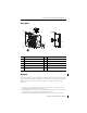
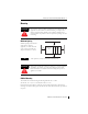
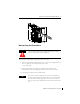
MicroLogix 1200 Isolated Relay Output Module 3 Description 9 1a 1a 7 3 6 2 6 5 8 1b 4 1b 2 Item Description Item Description 1a upper panel mounting tab 5 bus connector cover 1b lower panel mounting tab 6 flat ribbon cable with bus connector (female) 2 power diagnostic LED 7 3 module door with terminal identification label 8 DIN rail latch 4 bus connector with male pins pull loop 9 terminal block Overview 1762 I/O is suitable for use in an industrial environment when installe
MicroLogix 1200 Isolated Relay Output Module Prevent Electrostatic Discharge ATTENTION ! Electrostatic discharge can damage integrated circuits or semiconductors if you touch bus connector pins. Follow these guidelines when you handle the module: • • • • • • Touch a grounded object to discharge static potential. Wear an approved wrist-strap grounding device. Do not touch the bus connector or connector pins. Do not touch circuit components inside the module.
MicroLogix 1200 Isolated Relay Output Module 5 Mounting ATTENTION ! Do not remove protective debris strip until after the module and all other equipment near the module is mounted and wiring is complete. Once wiring is complete and the module is free of debris, carefully remove protective debris strip. Failure to remove strip before operating can cause overheating.
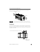
MicroLogix 1200 Isolated Relay Output Module Use DIN rail end anchors (Allen-Bradley part number 1492-EA35 or 1492-EAH35) for environments with vibration or shock concerns. End Anchor End Anchor TIP For environments with extreme vibration and shock concerns, use the panel mounting method described below, instead of DIN rail mounting. Panel Mounting Use the dimensional template shown below to mount the module. The preferred mounting method is to use two M4 or #8 panhead screws per module. M3.
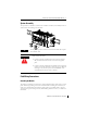
MicroLogix 1200 Isolated Relay Output Module 7 System Assembly The expansion I/O module is attached to the controller or another I/O module by means of a ribbon cable after mounting as shown below. TIP WARNING ! Use the pull loop on the connector to disconnect modules. Do not pull on the ribbon cable. EXPLOSION HAZARD • In Class I, Division 2 applications, the bus connector must be fully seated and the bus connector cover must be snapped in place.
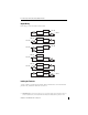
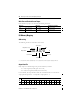
MicroLogix 1200 Isolated Relay Output Module Output Wiring Basic wiring(1) of the 1762-OX6I is shown below. L1-0 L1 OR +DC OUT0 N.C. L1 OR +DC OUT0 N.O. CR OUT1 N.C. CR L1-1 OUT1 N.O. L2 OR -DC L1-2 L2 OR -DC L2 OR -DC CR L1 OR +DC OUT2 N.C. OUT2 N.O. L1 OR +DC L2 OR -DC CR L1 OR +DC L1-3 OUT3 N.C. OUT3 N.O. L1-4 OUT4 N.C. CR OUT4 N.O. L2 OR -DC L1-5 CR L1 OR +DC OUT5 N.C. OUT5 N.O. L2 OR -DC Labeling the Terminals A write-on label is provided with the module.
MicroLogix 1200 Isolated Relay Output Module 9 Wiring the Finger-Safe Terminal Block ATTENTION ! Be careful when stripping wires. Wire fragments that fall into a module could cause damage when power is applied. Once wiring is complete, ensure the module is free of all metal fragments. When wiring the terminal block, keep the finger-safe cover in place. 1. Route the wire under the terminal pressure plate. You can use the stripped end of the wire or a spade lug. The terminals will accept a 6.35 mm (0.
MicroLogix 1200 Isolated Relay Output Module Wire Size and Terminal Screw Torque Each terminal accepts up to two wires with the following restrictions: Wire Type Wire Size Terminal Screw Torque Solid Cu-90 °C (194 °F) 14…22 AWG 0.904 Nm (8 lb-in) Stranded Cu-90 °C (194 °F) 16…22 AWG 0.904 Nm (8 lb-in) I/O Memory Mapping Addressing The addressing scheme for 1762-OX6I is shown below. Slot Number (1) Word Output Data File (0) O0:x.
MicroLogix 1200 Isolated Relay Output Module 11 Specifications General Specifications Specification Value Dimensions, H x W x D 90 x 40 x 87 mm height including mounting tabs is 110 mm 3.54 x 1.58 x 3.43 in. height including mounting tabs is 4.33 in. Approximate Shipping Weight (with carton) 220 g (0.485 lbs.
MicroLogix 1200 Isolated Relay Output Module Certifications Certification (when product is Value marked)(1) c-UL-us UL Listed Industrial Control Equipment, certified for US and Canada. See UL File E322657 UL Listed for Class I, Division 2 Group A,B,C,D Hazardous Locations, certified for U.S and Canada. See UL File E334470. CE European Union 2004/108/EC EMC Directive, compliant with: EN 61326-1; Meas./Control/Lab.
MicroLogix 1200 Isolated Relay Output Module 13 Output Specifications Specification Value Isolated Groups Outputs 0 to 5: Individually isolated Output Group to Backplane Isolation Verified by one of the following dielectric tests: 1836V AC for 1 second or 2596V DC for 2 seconds. 265V AC working voltage (IEC Class 2 reinforced insulation) Output Group to Output Group Isolation Verified by one of the following dielectric tests: 1836V AC for 1 second or 2596V DC for 2 seconds.
MicroLogix 1200 Isolated Relay Output Module Module Load Ratings Volts (max.) Controlled Load (Current) per Module (max.) 240V AC 12 A(1) 120V AC 12 A(1) 125V DC 2.4 A 24V DC 30 A(2) (1) (2) Current per relay limited to 6A at ambient temperatures above 40°C. 24A in ambient temperatures above 40°C. Limited by ambient temperature and the number of relays controlling loads. See below. IMPORTANT Controller must be operated within Relay Contact Ratings (page 13) and Module Load Ratings (above).
MicroLogix 1200 Isolated Relay Output Module 15 North American Hazardous Location Approval This equipment is suitable for use in Class I, Division 2, Groups A, B, C, D or non-hazardous locations only. The following WARNING statement applies to use in hazardous locations.
Rockwell Automation Support Rockwell Automation provides technical information on the Web to assist you in using its products. At http://www.rockwellautomation.com/support/, you can find technical manuals, a knowledge base of FAQs, technical and application notes, sample code and links to software service packs, and a MySupport feature that you can customize to make the best use of these tools.