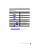
Installation Instructions MicroLogix 1762-OV32T Solid State 24V DC Sink Output Module Catalog Number 1762-OV32T Table of Contents Topic Page Important User Information 2 North American Hazardous Location Approval 4 Additional Resources 5 Overview 6 Module Description 7 Mount the Module 8 Field Wiring Connections 11 Wiring Options for the I/O Module 13 Labeling for the 1492 Interface Module 14 Assemble the Wire Contacts 15 Specifications 17
MicroLogix 1762-OV32T Solid State 24V DC Sink Output Module Important User Information Solid state equipment has operational characteristics differing from those of electromechanical equipment. Safety Guidelines for the Application, Installation and Maintenance of Solid State Controls (Publication SGI-1.1 available from your local Rockwell Automation sales office or online at http://literature.rockwellautomation.
MicroLogix 1762-OV32T Solid State 24V DC Sink Output Module 3 Environment and Enclosure ATTENTION This equipment is intended for use in a Pollution Degree 2 industrial environment, in overvoltage Category II applications (as defined in IEC 60664-1), at altitudes up to 2000 m (6562 ft) without derating.This equipment is considered Group 1, Class A industrial equipment according to IEC/CISPR 11.
MicroLogix 1762-OV32T Solid State 24V DC Sink Output Module North American Hazardous Location Approval The following modules are North American Hazardous Location approved: 1762-OV32T The following information applies when operating this equipment in hazardous locations: Informations sur l’utilisation de cet équipement en environnements dangereux: Products marked "CL I, DIV 2, GP A, B, C, D" are suitable for use in Class I Division 2 Groups A, B, C, D, Hazardous Locations and nonhazardous locations on
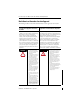
MicroLogix 1762-OV32T Solid State 24V DC Sink Output Module 5 Additional Resources Resource Description MicroLogix 1100 Programmable Controllers User Manual, publication 1763-UM001. A more detailed description of how to install and use your MicroLogix 1100 programmable controller and expansion I/O system. MicroLogix 1200 Programmable Controllers User Manual, publication 1762-UM001.
MicroLogix 1762-OV32T Solid State 24V DC Sink Output Module Overview The 1762 output module is suitable for use in an industrial environment when installed in accordance with these instructions. Specifically, this equipment is intended for use in clean, dry environments (Pollution degree 2(1)) and to circuits not exceeding Over Voltage Category II(2) (IEC 60664-1)(3). Install your module using these installation instructions.
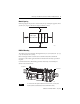
MicroLogix 1762-OV32T Solid State 24V DC Sink Output Module 7 Module Description 2 1a 3 4 9 8 8 5 1b 44910 7 6 Front view 44911 Left side view This equipment is sensitive to electrostatic discharge (ESD). Follow ESD prevention guidelines when handling this equipment.
MicroLogix 1762-OV32T Solid State 24V DC Sink Output Module Mount the Module General Considerations Most applications require installation in an industrial enclosure to reduce the effects of electrical interference and environmental exposure. Locate your controller as far as possible from power lines, load lines, and other sources of electrical noise such as hard-contact switches, relays, and ac motor drives.
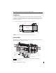
MicroLogix 1762-OV32T Solid State 24V DC Sink Output Module 9 Module Spacing Maintain spacing from objects such as enclosure walls, wireways and adjacent equipment. Allow 50.8 mm (2 in.) of space on all sides for adequate ventilation, as shown: 1762 I/O Side 1762 I/O MicroLogix 1100/1200/1400 1762 I/O Top Side Bottom 44913 DIN Rail Mounting The module can be mounted using the following DIN rails: 35 x 7.5 mm (EN 50 022 - 35 x 7.5) or 35 x 15 mm (EN 50 022 - 35 x 15).
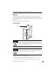
MicroLogix 1762-OV32T Solid State 24V DC Sink Output Module Panel Mounting Use the dimensional template shown below to mount the module. The preferred mounting method is to use two M4 (#8) panhead screws per module. M3.5 (#6) panhead screws may also be used, but a washer may be needed to ensure a good mechanical contact. Mounting screws are required on every module. For more than two I/O modules: measure (number of modules - 1) x 40 mm (1.59 in.) 95 (3.74) 40.4 (1.
MicroLogix 1762-OV32T Solid State 24V DC Sink Output Module 11 Field Wiring Connections Grounding the Module In solid-state control systems, grounding and wire routing helps limit the effects of noise due to electromagnetic interference (EMI). Run the ground connection from the ground screw of the controller to the ground bus prior to connecting any devices. Use AWG #14 wire. For AC-powered controllers, this connection must be made for safety purposes.
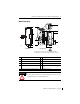
MicroLogix 1762-OV32T Solid State 24V DC Sink Output Module Output Wiring Basic wiring of output devices to the 1762-OV32T is shown below. Basic Wiring of the 1762-OV32T Module +VDC 1 +VDC 2 +VDC 1 +VDC 2 DC DC 44915 Simplified Output Circuit Diagram ~ +VDC OUT DC COM 31560 A write-on label is provided with the module. Mark the identification of each terminal with permanent ink, and slide the label back into the door.
MicroLogix 1762-OV32T Solid State 24V DC Sink Output Module 13 Wiring Options for the I/O Module Included with your 32-point output module is a keyed 40-pin female connector and crimp type pins. These components allow you to wire I/O devices to the module using a 40-conductor cable or individual wires. Refer to Assemble the Wire Contacts on page 15 for more information on connector/pin assembly instructions.
MicroLogix 1762-OV32T Solid State 24V DC Sink Output Module Labeling for the 1492 Interface Module Several different stick-on label sets are provided on a single card with 1492 Interface Modules. Each label set is identified with an I/O module catalog number and words upper and lower to identify which terminal strip the label should be affixed to. The following table identifies the 1762-OV32T 32-point labels and their location on the interface module.
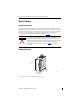
MicroLogix 1762-OV32T Solid State 24V DC Sink Output Module 15 Assemble the Wire Contacts 1. Strip the wire insulation to expose 4 mm (5/32 in.) of wire. Crimp pins can accept 22...26 AWG wire. ATTENTION Be careful when stripping wires. Wire fragments that fall into the module could cause damage. Once wiring is complete, be sure the module is free of all metal fragments before removing the protective debris strip. Failure to remove the strip before operating can cause overheating. 2.
MicroLogix 1762-OV32T Solid State 24V DC Sink Output Module I/O Memory Mapping For each output module, slot x, words 0...1 in the output data file contain the control program’s directed state of the digital output points.
MicroLogix 1762-OV32T Solid State 24V DC Sink Output Module 17 Specifications General Specifications Attribute Value Number of outputs 32 Dimensions, HxWxD 90 x 40.4 x 87 mm (3.54 x 1.59 x 3.43 in.) Shipping weight, approx. 200 g (7.05 oz) Bus current draw, max 175 mA @ 5V DC 0 mA @ 24V DC Heat dissipation 2.7 W @ 26.
MicroLogix 1762-OV32T Solid State 24V DC Sink Output Module Output Specifications Attribute Value Continuous current, per common, max 2.0 A @ 60 °C (140 °F) Continuous current, per module, max 4.0 A @ 60 °C (140 °F) Surge current, max 2.
MicroLogix 1762-OV32T Solid State 24V DC Sink Output Module 19 Environmental Specifications Attribute Value EFT/B immunity IEC 61000-4-4: ±2 kV at 5 kHz on signal ports Surge transient immunity IEC 61000-4-5: ±1 kV line-line(DM) and ±2 kV line-earth(CM) on signal ports Conducted RF immunity IEC 61000-4-6: 10V rms with 1 kHz sine-wave 80% AM from 150 kHz...
Rockwell Automation Support Rockwell Automation provides technical information on the Web to assist you in using its products. At http://www.rockwellautomation.com/support/, you can find technical manuals, a knowledge base of FAQs, technical and application notes, sample code and links to software service packs, and a MySupport feature that you can customize to make the best use of these tools.