Installation Instructions MicroLogix 1762-OB8 Solid-State 24V DC Source Output Module Catalog Number 1762-OB8 Table of Contents Topic Page Description 3 Installation 4 Mounting 5 System Assembly 7 Field Wiring Connections 8 I/O Memory Mapping 10 Specifications 11 North American Hazardous Location Approval 14 Publication 1762-IN008B-EN-P - July 2013
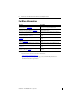
MicroLogix 1762-OB8 Solid-State 24V DC Source Output Module For More Information Resource Description MicroLogix 1200 Programmable Controllers User Manual, publication 1762-UM001. Information on installing, wiring, and operating a MicroLogix 1200 Programmable Controller MicroLogix 1200 Programmable Controllers Installation Instructions, publication 1762-IN006. Installation guide for the MicroLogix 1200 Programmable Controller.
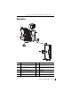
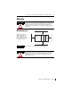
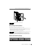
MicroLogix 1762-OB8 Solid-State 24V DC Source Output Module 3 Description 1a 9 7 3 6 5 1b 4 2 1a 6 2 8 Item Description Item Description 1a upper panel mounting tab 5 bus connector cover 1b lower panel mounting tab 6 flat ribbon cable with bus connector (female pins) 2 I/O diagnostic LEDs 7 terminal block 3 module door with terminal identification label 8 DIN rail latch 4 bus connector with male pins 9 pull loop 1b Publication 1762-IN008B-EN-P - July 2013
MicroLogix 1762-OB8 Solid-State 24V DC Source Output Module Installation 1762 I/O is suitable for use in an industrial environment when installed in accordance with these instructions. Specifically, this equipment is intended for use in clean, dry environments (Pollution degree 2(1)) and to circuits not exceeding Over Voltage Category II(2) (IEC 60664-1).
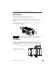
MicroLogix 1762-OB8 Solid-State 24V DC Source Output Module 5 Mounting Do not remove protective debris strip until after the module and all other equipment near the module is mounted and wiring is complete. Once wiring is complete and the module is free of debris, carefully remove protective debris strip. Failure to remove strip before operating can cause overheating. Minimum Spacing MicroLogix 1200 1762 I/O Side 1762 I/O Maintain spacing from enclosure walls, wireways, adjacent equipment, etc.
MicroLogix 1762-OB8 Solid-State 24V DC Source Output Module DIN Rail Mounting The module can be mounted using the following DIN rails: 35 x 7.5 mm (EN 50 022 - 35 x 7.5) or 35 x 15 mm (EN 50 022 - 35 x 15). Before mounting the module on a DIN rail, close the DIN rail latch. Press the DIN rail mounting area of the module against the DIN rail. The latch will momentarily open and lock into place.
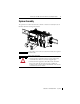
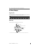
MicroLogix 1762-OB8 Solid-State 24V DC Source Output Module 7 System Assembly The expansion I/O module is attached to the controller or another I/O module by means of a flat ribbon cable after mounting as shown below. TIP ATTENTION Use the pull loop on the connector to disconnect modules. Do not pull on the ribbon cable. EXPLOSION HAZARD • In Class I, Division 2 applications, the bus connector must be fully seated and the bus connector cover must be snapped in place.
MicroLogix 1762-OB8 Solid-State 24V DC Source Output Module Field Wiring Connections Grounding the Module This product is intended to be mounted to a well-grounded mounting surface such as a metal panel. Refer to Industrial Automation Wiring and Grounding Guidelines, Allen-Bradley publication 1770-4.1, for additional information. Output Wiring Basic wiring of the 1762-OB8 is shown below.
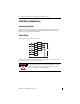
MicroLogix 1762-OB8 Solid-State 24V DC Source Output Module TIP 9 Finger-safe cover not shown for clarity. Wiring the Finger-Safe Terminal Block When wiring the terminal block, keep the finger-safe cover in place. 1. Route the wire under the terminal pressure plate. You can use the stripped end of the wire or a spade lug. The terminals will accept a 6.35 mm (0.25 in.) spade lug. 2. Tighten the terminal screw making sure the pressure plate secures the wire.
MicroLogix 1762-OB8 Solid-State 24V DC Source Output Module I/O Memory Mapping Output Data File Word For each output module, the output data file contains the controller-directed state of the discrete output points. Bit positions 0…7 correspond to output terminals 0…7.
MicroLogix 1762-OB8 Solid-State 24V DC Source Output Module 11 Specifications General Specifications Specification Value Dimensions, HxWxD 90 x 40.4 x 87 mm (height including mounting tabs is 110 mm) 3.54 x 1.59 x 3.43 in. (height including mounting tabs is 4.33 in.) Approximate Shipping Weight (with carton) 210 g (0.46 lbs.
MicroLogix 1762-OB8 Solid-State 24V DC Source Output Module Output Specifications Specification 1762-OB8 Voltage Category 24V DC Operating Voltage Range 20.4…26.4V DC Number of Outputs 8 Bus Current Draw (max.) 115 mA @ 5V DC (0.575W) Heat Dissipation (max.) 1.61 Total Watts Signal Delay (max.) – resistive load On Delay: 0.1 ms Off Delay: 1.0ms Off-State Leakage (max.) 1.0 mA On-State Current (min.) 1.0 mA On-State Volage Drop (max.) 1.0V DC Continuous Current per Point (max.) 0.
MicroLogix 1762-OB8 Solid-State 24V DC Source Output Module 13 Certifications Certification (when Value product is marked)(1) c-UL-us UL Listed Industrial Control Equipment, certified for US and Canada. UL Listed for Class I, Division 2 Group A,B,C,D Hazardous Locations, certified for U.S. and Canada. See UL File E334470. CE European Union 2004/108/EC EMC Directive, compliant with: EN 61326-1; Meas./Control/Lab.
MicroLogix 1762-OB8 Solid-State 24V DC Source Output Module North American Hazardous Location Approval The following modules are North American Hazardous Location approved: 1762-OB8 The following information applies when operating this equipment in hazardous locations: Informations sur l’utilisation de cet équipement en environnements dangereux: Products marked "CL I, DIV 2, GP A, B, C, D" are suitable for use in Class I Division 2 Groups A, B, C, D, Hazardous Locations and nonhazardous locations onl
MicroLogix 1762-OB8 Solid-State 24V DC Source Output Module 15 Notes: Publication 1762-IN008B-EN-P - July 2013
Rockwell Automation Support Rockwell Automation provides technical information on the Web to assist you in using its products. At http://www.rockwellautomation.com/support/, you can find technical manuals, a knowledge base of FAQs, technical and application notes, sample code and links to software service packs, and a MySupport feature that you can customize to make the best use of these tools.