
Installation Instructions Manual

22 MicroLogix 1200 Programmable Controllers
Publication 1762-IN006C-EN-P - September 2009
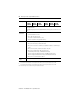
Shock Operating: 30G; 3 pulses each direction, each axis
Relay Operation: 7G
Non-Operating: 50G panel mounted (40G DIN Rail mounted); 3 pulses each direction, each
axis
Agency
Certification
• UL 508
• C-UL under CSA C22.2 no. 142
• Class I, Div. 2, Groups A, B, C, D
(UL 1604, C-UL under CSA C22.2 no. 213)
• CE/C-Tick compliant for all applicable directives
Electrical/EMC The controller has passed testing at the following levels:
• IEC1000-4-2: 4 kV contact, 8 kV air, 4 kV indirect
• IEC1000-4-3: 10V/m, 80 to 1000 MHz, 80% amplitude modulation, +900 MHz keyed
carrier
• IEC1000-4-4: 2 kV, 5 kHz; communications cable: 1 kV, 5 kHz
• IEC1000-4-5: communications cable 1 kV galvanic gun
I/O: 2 kV CM (common mode), 1 kV DM (differential mode)
AC Power Supply: 4 kV CM (common mode), 2 kV DM (differential mode)
DC Power Supply: 500V CM (common mode), 500V DM (differential mode)
• IEC1000-4-6: 10V, communications cable 3V
Terminal Screw
Torque
0.791 Nm (7 in-lb) rated
(1)
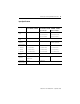
Do not allow the total load power consumed by the 5V dc, 24V dc, and sensor power outputs to exceed 12W.
(2)
Do not allow the total load power consumed by the 5V dc, 24V dc, and sensor power outputs to exceed 16W.
Refer to the MicroLogix 1200 User Manual for system validation worksheets.
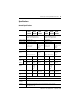
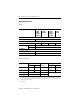
Description 1762-
L24AWA,
L24AWAR
L24BWA,
L24BWAR
L24BXB,
L24BXBR
40AWA,
40AWAR
L40BWA,
L40BWAR
L40BXB,
L40BXBR