
Installation Instructions Manual

MicroLogix 1200 Programmable Controllers 15
Publication 1762-IN006C-EN-P - September 2009
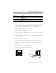
For detailed information on using expansion I/O, refer to the installation instructions for
your expansion module.
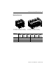
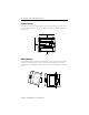
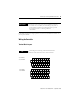
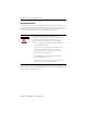
Wiring the Controller
Terminal Block Layouts
IMPORTANT
Ensure that your system power supply is sufficient to support
the number of I/O modules you are installing in the system. A
system loading worksheet is provided in the MicroLogix 1200
Programmable Controllers User Manual, publication
1762-UM001.
TIP
The shading in the following terminal block illustrations
indicates which terminals are tied to which commons.
VAC
L1
VAC
NEUT
VAC
DC 0
VAC
DC 1
VAC
DC 2
OUT 3 VAC
DC 4
OUT 4 OUT 7 OUT 9
OUT 0 OUT 1 OUT 2 VAC
DC 3
OUT 5 OUT 6 OUT 8
IN 0 IN 2 IN 5 IN 7 IN 9
COM
1
IN 11 IN 13
NC
COM
0
IN 1 IN 3 IN 4 IN 6 IN 8 IN 10 IN 12
NC
1762-L24AWA,
1762-L24AWAR
VAC
L1
VAC
NEUT
VAC
DC 0
OUT 0
VAC
DC 1
OUT 1
VAC
DC 2
OUT 2
VAC
DC 3
OUT 3
VAC
DC 4
OUT 4
OUT 5
OUT 6
OUT 7
OUT 8
OUT 9
+24
VDC
24
COM
IN 0 IN 2 IN 5 IN 7 IN 9
COM
1
IN 11 IN 13
COM
0
IN 1 IN 3 IN 4 IN 6 IN 8 IN 10 IN 12
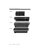
1762-L24BWA,
1762-L24BWAR