Installation Instructions MicroLogix™ 1200 Programmable Controllers (Cat. No. 1762-L24AWA, 1762-L24BWA, 1762-L24BXB, 1762-L40AWA, 1762-L40BWA, 1762-L40BXB, 1762-L24AWAR, 1762-L24BWAR, 1762-L24BXBR, 1762-L40AWAR, 1762-L40BWAR, 1762-L40BXBR) http://literature.rockwellautomation.com/idc/groups/literature/documents/in/1 762-in006_-mu-p.pdf FR Cette publication est disponible en français sous forme électronique (fichier PDF). Pour la télécharger, rendez-vous sur la page Internet indiquée ci-dessus.
Installation Instructions MicroLogix 1200 Programmable Controllers (Cat. No. 1762-L24AWA, 1762-L24BWA, 1762-L24BXB, 1762-L40AWA, 1762-L40BWA, 1762-L40BXB, 1762-L24AWAR, 1762-L24BWAR, 1762-L24BXBR, 1762-L40AWAR, 1762-L40BWAR, 1762-L40BXBR) Inside . . . Important User Information ................................................................................. 4 For More Information ........................................................................................... 5 Overview ......................
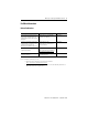
MicroLogix 1200 Programmable Controllers Important User Information Solid state equipment has operational characteristics differing from those of electromechanical equipment. Safety Guidelines for the Application, Installation and Maintenance of Solid State Controls (Publication SGI-1.1 available from your local Rockwell Automation sales office or online at http://www.ab.com/manuals/gi) describes some important differences between solid state equipment and hard-wired electromechanical devices.
MicroLogix 1200 Programmable Controllers 5 For More Information Related Publications For Refer to this Document Pub. No. A more detailed description of how to install and use your MicroLogix 1200 programmable controller and expansion I/O system. MicroLogix™ 1200 Programmable Controllers User Manual 1762-UM001 A reference manual that contains data and function files, instruction set, and troubleshooting information for MicroLogix 1200 and MicroLogix 1500.
MicroLogix 1200 Programmable Controllers Overview MicroLogix™ 1200 Controllers are suitable for use in an industrial environment when installed in accordance with these instructions. Specifically, this equipment is intended for use in clean, dry environments (Pollution degree 2(1)) and to circuits not exceeding Over Voltage Category II(2) (IEC 60664-1).(3) Install your controller using these installation instructions.
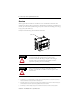
MicroLogix 1200 Programmable Controllers 7 Controller Description 7 6 10 8 2 0 1 5 12 COM 3 9 4 7 11 Item Description Item Description 1 Terminal Blocks 7 Terminal Doors and Label 1 (Removable Terminal Blocks on 40-point controllers only) 2 Bus Connector Interface to Expansion I/O 8 Trim Pots 3 Input LEDs 9 Default Communications Push Button 4 Output LEDs 10 Memory Module Port Cover(1) -orMemory Module and/or Real Time Clock(2) 5 Communication Port (Channel 0) 11 DIN Rail
MicroLogix 1200 Programmable Controllers Catalog Number Description Input Power Inputs Outputs 1762-L24AWA, -L24AWAR 120/240V ac (14) 120V ac (10) relay 1762-L24BWA, -L24BWAR 120/240V ac (10) 24V dc (10) relay (4) fast 24V dc 1762-L24BXB, -L24BXBR 24V dc (10) 24V dc (5) relay, (4) 24V dc FET (4) fast 24V dc (1) high-speed 24V dc FET 1762-L40AWA, -L40AWAR 120/240V ac (24) 120V ac (16) relay 1762-L40BWA, -L40BWAR 120/240V ac (20) 24V dc (16) relay 1762-L40BXB, -L40BXBR 24V dc (
MicroLogix 1200 Programmable Controllers Environment Classification Communication Cables Class I, Division 2 Hazardous Environment 1761-CBL-PM02 Series C or later 9 1761-CBL-HM02 Series C or later 1761-CBL-AM00 Series C or later 1761-CBL-AP00 Series C or later 2707-NC8 Series B or later 2707-NC10 Series B or later 2707-NC11 Series B or later Environnements dangereux Cet équipement est conçu pour être utilisé dans des environnements de Classe I, Division 2, Groupes A, B, C, D ou non dangereux.
MicroLogix 1200 Programmable Controllers Classification des environnements Câbles de communication Environnement dangereux de Classe I, Division 2 1761-CBL-PM02 série C ou ultérieure 1761-CBL-HM02 série C ou ultérieure 1761-CBL-AM00 série C ou ultérieure 1761-CBL-AP00 série C ou ultérieure 707-NC8 série B ou ultérieure 2707-NC10 série B ou ultérieure 2707-NC11 série B ou ultérieure Mounting the Controller General Considerations Most applications require installation in an industrial enclosure to re
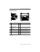
MicroLogix 1200 Programmable Controllers 11 Mounting Dimensions C C A B A 1762-L24AWA, 1762-L24BWA, 1762-L24BXB, 1762-L24AWAR, 1762-L24BWAR, 1762-L24BXBR Dimension B 1762-L40AWA, 1762-L40BWA, 1762-L40BXB, 1762-L40AWAR, 1762-L40BWAR, 1762-L40BXBR 1762L24AWA, L24AWAR L24BWA, L24BWAR L24BXB, L24BXBR L40AWA, L40AWAR L40BWA, L40BWAR A 90 mm (3.5 in.) B 110 mm (4.33 in.) 160 mm (6.30 in.) C 87 mm (3.43 in.) 87 mm (3.43 in.) L40BXB, L40BXBR 90 mm (3.5 in.
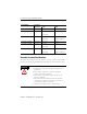
MicroLogix 1200 Programmable Controllers Controller Spacing The controller mounts horizontally, with the expansion I/O extending to the right of the controller. Allow 50 mm (2 in.) of space on all but the right side for adequate ventilation, as shown below. Top Side Bottom DIN Rail Mounting The maximum extension of the latch is 14 mm (0.55 in.) in the open position. A flat-blade screwdriver is required for removal of the controller. The controller can be mounted to EN50022-35x7.
MicroLogix 1200 Programmable Controllers Dimension Height A 90 mm (3.5 in.) B 27.5 mm (1.08 in.) C 27.5 mm (1.08 in.) 13 To install your controller on the DIN rail: 1. Mount your DIN rail. (Make sure that the placement of the controller on the DIN rail meets the recommended spacing requirements, see Controller Spacing on page 12. Refer to the mounting template inside the back cover of this document.) 2. Close the DIN latch, if it is open. 3. Hook the top slot over the DIN rail. 4.
MicroLogix 1200 Programmable Controllers Panel Mounting Mount to panel using #8 or M4 screws. To install your controller using mounting screws: 1. Remove the mounting template from inside the back cover of this document. 2. Secure the template to the mounting surface. (Make sure your controller is spaced properly. See Controller Spacing on page 12.) 3. Drill holes through the template. 4. Remove the mounting template. 5. Mount the controller. Mounting Template 6.
MicroLogix 1200 Programmable Controllers IMPORTANT 15 Ensure that your system power supply is sufficient to support the number of I/O modules you are installing in the system. A system loading worksheet is provided in the MicroLogix 1200 Programmable Controllers User Manual, publication 1762-UM001. For detailed information on using expansion I/O, refer to the installation instructions for your expansion module.
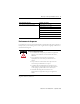
MicroLogix 1200 Programmable Controllers 1762-L24BXB, 1762-L24BXBR NC IN 0 COM 0 NC +24 VDC VDC NEUT NC NC IN 0 24 COM IN 12 OUT 0 OUT 1 OUT 2 OUT 4 OUT 6 OUT 8 VAC DC 1 COM 1 IN 3 VAC L1 VAC NEUT OUT 0 VAC L1 VAC NEUT OUT 0 VAC DC 0 1762-L40BXB, 1762-L40BXBR NC NC COM 0 IN 0 IN 2 IN 1 +24 VDC VDC NEUT OUT 0 VAC DC 0 COM 1 VAC DC 1 OUT 5 COM 2 OUT 7 OUT 9 IN 5 IN 7 IN 8 IN 10 IN 12 IN 14 IN 18 IN 20 IN 22 IN 13 IN 15 IN 17 IN 19 IN 21 OUT 1 OUT 2
MicroLogix 1200 Programmable Controllers 17 Wire Requirements Wire Type Wire Size (2 wire maximum per terminal screw) Solid Cu-90°C (194°F) #14 to #22 AWG Stranded Cu-90°C (194°F) #16 to #22 AWG Wiring torque = 0.791 Nm (7 in-lb) rated ATTENTION Be careful when stripping wires. Wire fragments that fall into the controller could cause damage. Once wiring is complete, be sure the controller is free of all metal fragments before removing the protective debris strip.
MicroLogix 1200 Programmable Controllers Spade Lug Recommendation The diameter of the terminal screw head is 5.5 mm (0.220 in.). The input and output terminals of the MicroLogix 1200 controller are designed for the following spade lugs. The terminals will accept a 6.35mm (0.25 in.) wide spade (standard for #6 screw for up to 14 AWG) or a 4 mm (metric #4) fork terminal. When using spade lugs, use a small, flat-blade screwdriver to pry the finger-safe cover from the terminal blocks.
MicroLogix 1200 Programmable Controllers 19 Surge Suppression ATTENTION Inductive load devices such as motor starters and solenoids require the use of some type of surge suppression to protect the controller output. Switching inductive loads without surge suppression can significantly reduce the life of relay contacts or damage transistor outputs.
MicroLogix 1200 Programmable Controllers Grounding the Controller In solid-state control systems, grounding and wire routing helps limit the effects of noise due to electromagnetic interference (EMI). Run the ground connection from the ground screw of the controller to the ground bus prior to connecting any devices. Use AWG #14 wire. For AC-powered controllers, this connection must be made for safety purposes.
MicroLogix 1200 Programmable Controllers 21 Specifications General Specifications Description 1762L24AWA, L24AWAR L24BWA, L24BWAR L24BXB, L24BXBR 40AWA, 40AWAR L40BWA, L40BWAR L40BXB, L40BXBR Height: 90 mm, 104 mm (with DIN latch open) Width: 110 mm, Depth: 87 mm Height: 90 mm 104 mm (with DIN latch open) Width: 160 mm, Depth: 87 mm Shipping Weight 0.9 kg (2.0 lbs) 1.1 kg (2.
MicroLogix 1200 Programmable Controllers Description 1762L24AWA, L24AWAR L24BWA, L24BWAR L24BXB, L24BXBR 40AWA, 40AWAR L40BWA, L40BWAR L40BXB, L40BXBR Shock Operating: 30G; 3 pulses each direction, each axis Relay Operation: 7G Non-Operating: 50G panel mounted (40G DIN Rail mounted); 3 pulses each direction, each axis Agency Certification • UL 508 • C-UL under CSA C22.2 no. 142 • Class I, Div. 2, Groups A, B, C, D (UL 1604, C-UL under CSA C22.2 no.
MicroLogix 1200 Programmable Controllers 23 Input Specifications Description 1762-L24AWA, -L40AWA 1762-L24AWAR, -L40AWAR On-State Voltage Range 79 to 132V ac 1762-L24BWA, -L24BXB, -L40BWA, -L40BXB 1762-L24BWAR, -L24BXBR, -L40BWAR, -L40BXBR Inputs 0 through 3 Inputs 4 and higher 14 to 24V dc 10 to 24V dc (+10% at 55°C/131°F) (+25% at 30°C/86°F) (+10% at 55°C/131°F) (+25% at 30°C/86°F) Off-State Voltage Range 0 to 20V ac 0 to 5V dc Operating Frequency 47 Hz to 63 Hz 0 Hz to 20 kHz 0 Hz to 1
MicroLogix 1200 Programmable Controllers Output Specifications General Description 1762 -L24AWA -L24BWA -L24AWAR -L24BWAR -L24BXB -L24BXBR -L40AWA -L40BWA -L40AWAR -L40BWAR -L40BXB -L40BXBR 7.
MicroLogix 1200 Programmable Controllers 25 BXB FET Output Specifications Description General Operation Power Supply Voltage 24V dc ( -15%, +10%) High Speed Operation(1) (Output 2 Only) On-State Voltage Drop: • at maximum load current • 1V dc • Not Applicable • at maximum surge current • 2.5V dc • Not Applicable • maximum load • See graphs below. • 100 mA • minimum load • 1.0 mA • 10 mA • maximum leakage • 1.0 mA • 1.
MicroLogix 1200 Programmable Controllers Description General Operation High Speed Operation(1) (Output 2 Only) Turn-On Time (maximum) 0.1 msec 6 µsec Turn-Off Time (maximum) 1.0 msec 18 µsec Repeatability (maximum) n/a 2 µsec Drift (maximum) n/a 1 µsec per 5°C (9°F) (1) Output 2 is designed to provide increased functionality over the other FET outputs.
MicroLogix 1200 Programmable Controllers 27 Description 1762-L24BWA, 1762-L40BWA, 1762-L24BWAR, 1762-L40BWAR Power Supply Input to Backplane Isolation Verified by one of the following dielectric tests:1836V ac for 1 second or 2596V dc for 1 second 265V ac Working Voltage (IEC Class 2 reinforced insulation) Input Group to Backplane Isolation and Input Group to Input Group Isolation Verified by one of the following dielectric tests: 1200V ac for 1 second or 1697V dc for 1 second Output Group to Backpl
MicroLogix 1200 Programmable Controllers Notes: Publication 1762-IN006C-EN-P - September 2009
160.0 mm (6.299 in.) 25.81 mm (1.016 in.) 145.8 mm (5.739 in.) 95.86 mm (3.774 in.) 0.164 DIN rail center line. Ligne médiane du rail DIN. Mittellinie der DIN-Schiene. Línea central del riel DIN. Linea centrale della guida DIN. linha de centro do trilho DIN. Expansion I/O E/S d’extension d'extension d'E/S E/A Erweiterungsmodule l'espansione dei moduli I/O de expansión de E/S 99.97 mm (3.936 in.
0 0 INPUTS 1 2 1 3 2 4 3 5 4 6 5 7 6 8 7 9 8 10 11 12 13 3 2 4 3 5 4 6 5 7 6 8 7 9 8 10 9 11 12 13 9 0 2 1 OUTPUTS INPUTS 1 0 OUTPUTS L24BWA L24BWAR L24AWA L24AWAR
VAC L1 VAC DC 1 VAC DC 2 IN 5 IN 4 VAC DC3 VAC DC 4 OUT 7 OUT 9 IN 12 IN 13 IN 11 IN 10 IN 9 OUT 5 OUT 6 OUT 8 IN 7 IN 6 IN 8 OUT 3 OUT 4 VAC OUT 0 OUT 1 OUT 2 NEUT VAC DC 0 COM 1 IN 3 IN 2 IN 1 OUT 7 OUT 9 VAC DC 3 OUT 5 OUT 6 OUT 8 VAC DC 4 OUT 0 OUT 1 OUT 2 IN 0 COM 0 NC 1762-L24AWA NC VAC NEUT 1762-L24AWA VAC L1 OUT 3 OUT 4 VAC DC 2 IN 12 IN 13 VAC DC 1 IN 10 IN 11 IN 8 IN 9 IN 6 IN 7 IN 4 IN 5 IN 3 IN 2 COM 1 IN 1 VAC DC 0 IN 0 1762-L24BWA +24 VDC 24 COM 0 COM
0 0 INPUTS 1 2 2 OUTPUTS INPUTS 1 OUTPUTS 3 3 4 5 6 7 8 9 10 11 12 13 14 15 16 17 18 19 19 15 18 15 14 17 14 13 16 13 12 15 12 11 14 11 10 13 10 9 12 9 8 11 8 7 10 7 6 9 6 5 8 5 4 7 4 3 6 3 2 5 2 1 4 1 0 0 20 20 21 21 22 22 23 23 L40BWA L40BWAR L40AWA L40AWAR
NC VAC L1 COM 0 1762-L40AWA NC 1762-L40AWA VAC L1 1762-L40BWA COM 0 +24 VDC 24 COM 1762-L40BWA OUT 15 OUT 14 OUT 13 OUT 12 VAC DC 5 OUT 11 OUT 10 OUT 9 OUT 8 VAC DC 4 OUT 7 OUT 6 OUT 5 OUT 4 VAC DC 3 OUT 3 OUT 2 VAC DC 2 OUT 1 VAC DC 1 OUT 0 VAC DC 0 IN 23 IN 22 IN 21 IN 20 IN 19 IN 18 IN 17 IN 16 IN 15 IN 14 IN 13 IN 12 IN 11 IN 10 IN 9 IN 8 COM 2 IN 7 IN 6 IN 5 IN 4 COM 1 IN 3 IN 2 VAC NEUT IN 0 IN 1 OUT 15 OUT 14 OUT 13 OUT 12 VAC DC 5 OUT 11 OUT 10 OUT 9 OUT 8
0 2 3 4 5 6 7 8 9 10 11 12 9 13 10 14 11 15 12 16 13 17 14 18 15 19 11 12 13 8 10 9 7 9 8 6 8 7 5 7 6 4 6 5 3 5 4 2 4 3 1 3 2 0 2 1 20 21 22 23 L40BXB L40BXBR INPUTS 1 1 INPUTS OUTPUTS 0 0 OUTPUTS L24BXB L24BXBR
+24 VDC VDC NEUT OUT 9 OUT 8 OUT 7 VAC DC 3 COM 2 OUT 6 OUT 5 OUT 4 OUT 3 OUT 2 VDC 2 OUT 1 VAC DC 1 IN 12 IN 13 IN 10 IN 11 IN 8 IN 9 IN 6 IN 7 IN 4 IN 5 IN 3 COM 1 IN 1 OUT 15 OUT 14 OUT 13 OUT 12 VAC DC 4 OUT 11 OUT 10 VAC DC 3 COM 2 OUT 9 OUT 6 OUT 7 OUT 4 OUT 5 OUT 2 OUT 3 OUT 1 VDC 2 OUT 0 VAC DC 1 IN 23 IN 22 IN 21 IN 20 IN 19 IN 18 IN 17 IN 16 IN 15 IN 14 IN 13 VAC DC 0 IN 11 IN 12 IN 9 IN 10 COM 2 IN 8 IN 6 IN 7 IN 4 IN 5 IN 3 COM 1 IN 1 IN 2 VDC
Rockwell Automation Support Rockwell Automation provides technical information on the Web to assist you in using its products. At http://support.rockwellautomation.com, you can find technical manuals, a knowledge base of FAQs, technical and application notes, sample code and links to software service packs, and a MySupport feature that you can customize to make the best use of these tools.