
Instruction Manual

Publication 1762-UM001G-EN-P - March 2011
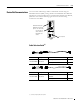
4-16 Communication Connections
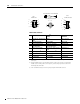
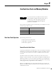
1761-CBL-AP00 or 1761-CBL-PM02
DB-9 RS-232
RS-485 connector
cable straight D connector
Port 1
Port 2
Port 3
6
7
8
9
1
2
3
4
5
4
1
2
5
876
3
6
5
4
3
2
1
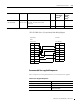
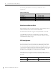
Table 4.8 AIC+ Terminals
Pin Port 1: DB-9 RS-232
Port 2
(2)
: (1761-CBL-PM02
cable)
(2) An 8-pin mini DIN connector is used for making connections to port 2. This connector is not commercially
available. If you are making a cable to connect to port 2, you must configure your cable to connect to the
Allen-Bradley cable shown above.
Port 3: RS-485
Connector
1 received line signal detector
(DCD)
24V dc chassis ground
2 received data (RxD) ground (GND) cable shield
3 transmitted data (TxD) request to send (RTS) signal ground
4
DTE ready (DTR)
(1)
(1) On port 1, pin 4 is electronically jumpered to pin 6. Whenever the AIC+ is powered on, pin 4 will match the
state of pin 6.
received data (RxD)
(3)
(3) In the 1761-CBL-PM02 cable, pins 4 and 6 are jumpered together within the DB-9 connector.
DH-485 data B
5 signal common (GND) received line signal detector
(DCD)
DH-485 data A
6
DCE ready (DSR)
(1)
clear to send (CTS)
(3)
termination
7 request to send (RTS) transmitted data (TxD) not applicable
8 clear to send (CTS) ground (GND) not applicable
9 not applicable not applicable not applicable