
Instruction Manual


Publication 1762-UM001G-EN-P - March 2011
Communication Connections 4-15
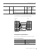
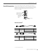
1761-CBL-PM02 Series C (or equivalent) Cable Wiring Diagram
Recommended User-supplied Components
These components can be purchased from your local electronics supplier.
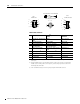
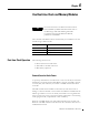
Cable Length Connections from to AIC+ External
Power Supply
Required
(1)
Power
Selection
Switch
Setting
(1)
1761-CBL-AS03
1761-CBL-AS09
3m (9.8 ft)
9.5m (31.17 ft)
SLC 500 Fixed,
SLC 5/01, SLC 5/02, and SLC 5/03
processors
port 3 yes external
PanelView 550 RJ45 port port 3 yes external
(1) External power supply required unless the AIC+ is powered by the device connected to port 2, then the selection switch should be set to cable.
Table 4.7 User Supplied Components
Component Recommended Model
external power supply and chassis ground power supply rated for 20.4 to 28.8V dc
NULL modem adapter standard AT
straight 9-25 pin RS-232 cable see table below for port information if
making own cables
Programming
Device
Controller
9-Pin D-Shell 8-Pin Mini Din
9RI 24V1
8CTS GND2
7RTS RTS3
6 DSR RXD 4
5GND DCD5
4DTR CTS6
3TXD TXD7
2RXD GND8
1DCD