
Instruction Manual

Publication 1762-UM001G-EN-P - March 2011
Wire Your Controller 3-17
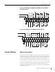
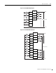
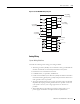
Figure 3.19 1762-L40AWA, 1762-L40BWA, 1762-L40AWAR, and 1762-L40BWAR
Output Wiring Diagram
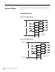
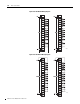
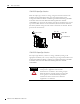
Figure 3.20 1762-L40BXB and 1762-L40BXBR Output Wiring Diagram
Controller I/O Wiring
Minimize Electrical Noise
Because of the variety of applications and environments where controllers are
installed and operating, it is impossible to ensure that all environmental noise
will be removed by input filters. To help reduce the effects of environmental
noise, install the MicroLogix 1200 system in a properly rated (NEMA)
enclosure. Make sure that the MicroLogix 1200 system is properly grounded.
A system may malfunction due to a change in the operating environment after
a period of time. We recommend periodically checking system operation,
particularly when new machinery or other noise sources are installed near the
Micrologix 1200 system.
CRCR
CR
CR
CR
CR
CR
CR
L2
L1
L1a L1b L1c
L2a L2b L2c
L2c
L2d L2f
L2f
L2e
L2e
L2d
L1d L1f
L1e
OUT
11
VAC
DC 4
VAC
NEUT
VAC
DC 0
VAC
DC 1
VAC
DC 2
OUT
3
OUT
46
OUT
OUT
9
OUT
14
OUT
12
OUT
15
VAC
L1
OUT
0
OUT
1
OUT
2
VAC
DC 3
OUT
7
OUT
5
OUT
8
OUT
13
OUT
10
VAC
DC 5
CRCR
CR
CR
CR
CR
CR
CR
-DC
-DCe
-DCe
+DCd
-DCd
-DCc
-DCc
-DCd
-DCa
+DC
-DCb
+DCe
+DCa +DCb
+DCc
OUT
11
OUT
VDC
NEUT
VAC
DC 0
VAC
DC 1
VDC
2
OUT
3
OUT
57
OUT
VAC
DC3
OUT
14
OUT
12
OUT
15
+24
VDC
OUT
0
OUT
1
OUT
2
OUT
8
COM OUT
13
OUT
10
VAC
DC 4
9
OUT
4
OUT
6
CR