
Instruction Manual

Publication 1762-UM001G-EN-P - March 2011
System Loading and Heat Dissipation F-9
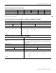
1762-OX6I 110 110
1762-IQ8OW6 110 80
Total Modules (6 maximum): Subtotal 2:
(1) Refer to your expansion I/O Installation Instructions for Current Requirements not listed in this table.
(2) Only applicable to Series B I/O modules.
Table F.14 Calculating the Current for Expansion I/O
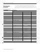
Table F.15 Validating Systems using 1762-L40AWA, 1762-L40BXB, 1762-L40AWAR or 1762-L40BXBR
Maximum Allowable Values Calculated Values
Current: Current (Subtotal 1 from Table F.13 + Subtotal 2 from Table F.14.):
600 mA at 5V dc 500 mA at 24V dc
System Loading: System Loading:
15 Watts
= (________ mA x 5V) + (________ mA x 24V)
= __________ mW + __________ mW
= __________ mW
= __________ W
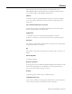
Table F.16 Validating Systems using 1762-L40BWA or 1762-L40BWAR
Maximum Allowable Values Calculated Values
Current for Devices Connected to the +24V dc Sensor
Supply:
Sum of all sensor currents
Include 1761-NET-AIC here rather than in Table F.13, if it is powered externally by
the sensor supply
400 mA at 24V dc mA at 24V dc
Current for MicroLogix Accessories and Expansion I/O: Current (Subtotal 1 from Table F.13 + Subtotal 2 from page Table F.14.):
600 mA at 5V dc 500 mA at 24V dc mA at 5 V dc mA at 24V dc
System Loading: System Loading:
16 Watts
= (________ mA x 24V) + (________ mA x 5V) + (________ mA x 24V)
= __________ mW + __________ mW + __________ mW
= __________ mW
= __________ W