
Instruction Manual

Publication 1762-UM001G-EN-P - March 2011
F-8 System Loading and Heat Dissipation
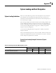
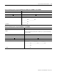
System Loading Worksheet
The tables below are provided for system loading validation for 40-point
Controllers. See System Current Loading Example Calculations (40-point
Controller) on page F-6.
Current Loading
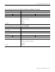
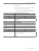
Table F.13 Calculating the Current for MicroLogix Accessories
Catalog Number Device Current Requirements Calculated Current
at 5V dc (mA) at 24V dc (mA) at 5V dc (mA) at 24V dc (mA)
1761-NET-AIC
(1)
when powered by the base unit
communications port, selector switch in the up position
0 120
Subtotal 1:
(1) This is an optional accessory. Current is consumed only if the accessory is installed.
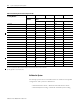
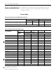
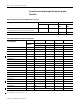
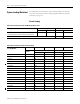
Table F.14 Calculating the Current for Expansion I/O
Catalog Number
(1)
n A B n x A n x B
Number of
Modules
Device Current Requirements Calculated Current
at 5V dc (mA) at 24V dc (mA) at 5V dc (mA) at 24V dc (mA)
1762-IA8 50 0
1762-IQ8 50 0
1762-IF4 40 50
1762-IF2OF2 40 105
1762-IQ16
70
(2)
0
1762-IQ32T 170 0
1762-IR4 40 50
1762-IT4 40 50
1762-OA8 115 0
1762-OB8 115 0
1762-OB16 175 0
1762-OB32T 175 0
1762-OF4 40 165
1762-OV32T 175 0
1762-OW8 80 90
1762-OW16
140
(2)
180
(2)