
Manual

Publication 1762-UM002A-EN-P - July 2002
Module Data, Status, and Channel Configuration 3-5
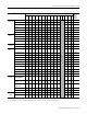
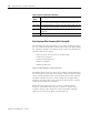
To Select
(1)
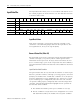
Make these bit settings
Decimal
Value
15 14 13 12 11 10 9 8 7 6 5 4 3 2 1 0
Filter
Frequency
10 Hz
Not Used
(2)
110 6
60 Hz
000 0
50 Hz
001 1
250Hz
011 3
500 Hz
100 4
1 kHz
101 5
Open
Circuit
Upscale
00 0
Downscale
01 32
Hold Last State
10 64
Zero
11 96
Tempera-
ture Units
Degrees C
0 0
Degrees F
1 128
Input
Type
Thermocouple
J
0000 0
Thermocouple K
0001 256
Thermocouple T
0010 512
Thermocouple E
0011 768
Thermocouple R
0100 1024
Thermocouple S
0101 1280
Thermocouple B
0110 1536
Thermocouple N
0111 1792
Thermocouple C
1000 2048
-50 to +50 mV
1001 2304
-100 to +100 mV
1010 2560
Data
Format
Raw/
Proportional
000 0
Engineering
Units
001 4096
Engineering
Units X 10
100 16384
Scaled-for-PID
010 8192
Percent Range
011 12288
Enable
Channel
Disable 0
0
Enable 1
-32768
(1) Default values are in bold type and are indicated by zero bit settings. For example, the default filter frequency is 60Hz.
(2) An attempt to write any non-valid (spare) bit configuration into any selection field results in a module configuration error.