
Manual

Publication 1762-UM002A-EN-P - July 2002
3-2 Module Data, Status, and Channel Configuration
Input Data File
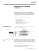
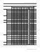
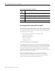
The input data table allows you to access module read data for use in
the control program, via word and bit access. The data table structure
is shown in table below.
Input Data Values
Data words 0 through 3 correspond to channels 0 through 3 and
contain the converted analog input data from the input device. The
most significant bit, bit 15, is the sign bit (SGN).
General Status Bits (S0 to S4)
Bits S0 through S3 of word 4 contain the general status information for
channels 0 through 3, respectively. Bit S4 contains general status
information for the CJC sensor. If set (1), these bits indicate an error
(over- or under-range, open-circuit or input data not valid condition)
associated with that channel. The data not valid condition is described
below.
Input Data Not Valid Condition
The general status bits S0 to S3 also indicate whether or not the input
data for a particular channel, 0 through 3, is being properly converted
(valid) by the module. This “invalid data” condition can occur (bit set)
when the download of a new configuration to a channel is accepted
by the module (proper configuration) but before the A/D converter
can provide valid (properly configured) data to the MicroLogix 1200
controller. The following information highlights the bit operation of
the Data Not Valid condition.
1. The default and module power-up bit condition is reset (0).
2. The bit condition is set (1) when a new configuration is received
and determined valid by the module. The set (1) bit condition
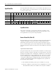
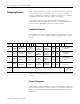
Word/Bit 15 14 13 12 11 10 9 8 7 6 5 4 3 2 1 0
0 SGN Analog Input Data Channel 0
1 SGN Analog Input Data Channel 1
2 SGN Analog Input Data Channel 2
3 SGN Analog Input Data Channel 3
4 Reserved OC4 OC3 OC2 OC1 OC0 Reserved S4 S3 S2 S1 S0
5 U0 O0U1O1U2O2U3O3U4O4 Reserved