
Manual

Publication 1762-UM002A-EN-P - July 2002
Installation and Wiring 2-9
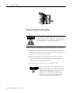
• If it is necessary to connect the shield drain wire at the module
end, connect it to earth ground using a panel or DIN rail
mounting screw.
• Refer to Industrial Automation Wiring and Grounding
Guidelines, Allen-Bradley publication 1770-4.1, for additional
information.
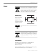
Noise Prevention
• Route field wiring away from any other wiring and as far as
possible from sources of electrical noise, such as motors,
transformers, contactors, and ac devices. As a general rule, allow
at least 15.2 cm (6 in.) of separation for every 120V of power.
• Routing field wiring in a grounded conduit can reduce electrical
noise.
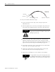
• If field wiring must cross ac or power cables, ensure that they
cross at right angles.
• To limit the pickup of electrical noise, keep thermocouple and
millivolt signal wires as far as possible from power and load
lines.
• If noise persists for a device, try grounding the opposite end of
the cable shield. (You can only ground one end at a time.)
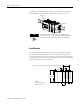
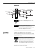
Wiring
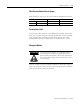
Terminal Block Layout
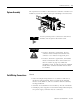
Labeling the Terminals
A write-on label is provided with the module. Mark the identification
of each terminal with permanent ink, and slide the label back into the
door.
IN1 -
IN1 +
IN 0 -
IN 0 +
IN2 -
IN2 +
CJC
CJC
IN3 -
IN3 +