
Manual

Publication 1762-UM002A-EN-P - July 2002
Overview 1-5
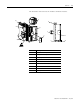
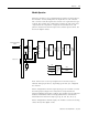
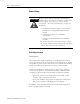
Module Operation
When the module receives a differential input from an analog device,
the module’s circuitry multiplexes the input into an A/D converter.
The converter reads the signal and converts it as required for the type
of input. The module also continuously samples the CJC sensor and
compensates for temperature changes at the terminal block cold
junction, between the thermocouple wire and the input channel. See
the block diagram below.
Each channel can receive input signals from a thermocouple or
millivolt analog input device, depending upon how you configured
the channel.
When configured for thermocouple input types, the module converts
the analog input voltages into cold-junction compensated and
linearized digital temperature readings. The module uses the National
Institute of Standards and Technology (NIST) ITS-90 standard for
linearization for all thermocouple types (J, K, T, E, R, S, B, N, C).
When configured for millivolt inputs, the module converts the analog
values directly into digital counts.
4 Thermocouple/mV
Inputs
1762 Bus ASIC
Optocoupler
A/D
Converter
Multiplexer
S-GND
Isolated Power
Supply
+5V
+24V
-15V
CJC Sensor
MCU
Terminal Block
MicroLogix 1200 Controller
+15V
A-GND
AIN +
AIN -
AIN +
AIN -