
Manual

Publication 1762-UM002A-EN-P - July 2002
Overview 1-3
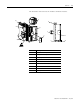
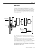
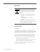
The illustration below shows the module’s hardware features.
1a
1b
5
2
3
9
4
6
7
1a
1b
2
6
8
Item Description
1a upper panel mounting tab
1b lower panel mounting tab
2 power diagnostic LED
3 module door with terminal identification label
5 bus connector cover
6 flat ribbon cable with bus connector (female)
7 terminal block
8 DIN rail latch
9 pull loop