
Instruction Manual
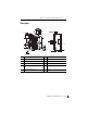
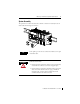
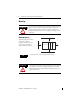
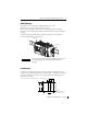
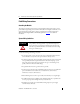
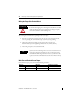
Table Of Contents
MicroLogix 1200 Thermocouple/mV Input Module 9
Publication 1762-IN013B-EN-P - June 2013
• Ground the shield drain wire at one end only. The typical location is the same point as
the sensor ground reference.
– For grounded thermocouples or millivolt sensors, this is at the sensor end.
– For insulated/ungrounded thermocouples, this is at the module end. Contact your
sensor manufacturer for additional details.
• If it is necessary to connect the shield drain at the module end, connect it to earth
ground using a panel or DIN rail mounting screw.
• Routing the field wiring in a grounded conduit can further reduce electrical noise.
Terminal Block Layout
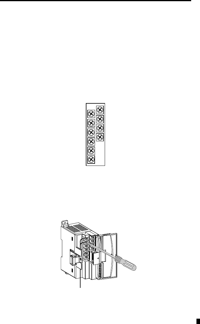
Labeling the Terminals
A write-on label is provided with the module. Mark the identification of each terminal with
permanent ink, and slide the label back into the door.
IN1 -
IN1 +
IN 0 -
IN 0 +
IN2 -
IN2 +
CJC
CJC
IN3 -
IN3 +