
Instruction Manual
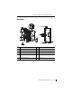
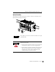
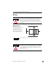
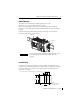
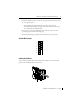
Table Of Contents
MicroLogix 1200 Thermocouple/mV Input Module 5
Publication 1762-IN013B-EN-P - June 2013
System Assembly
The expansion I/O module is attached to the controller or another I/O module by means of a
ribbon cable after mounting as shown below.
TIP
Use the pull loop on the connector to disconnect modules. Do not pull
on the ribbon cable.
WARNING
EXPLOSION HAZARD
• In Class I, Division 2 applications, the bus connector must be fully
seated and the bus connector cover must be snapped in place.
• In Class I, Division 2 applications, all modules must be mounted in
direct contact with each other as shown on
page 7. If DIN rail
mounting is used, an end stop must be installed ahead of the
controller and after the last 1762 I/O module.