
Instruction Manual
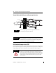
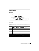
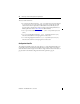
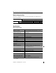
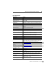
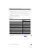
Table Of Contents
MicroLogix 1200 Thermocouple/mV Input Module 13
Publication 1762-IN013B-EN-P - June 2013
I/O Memory Mapping
A
ddressing
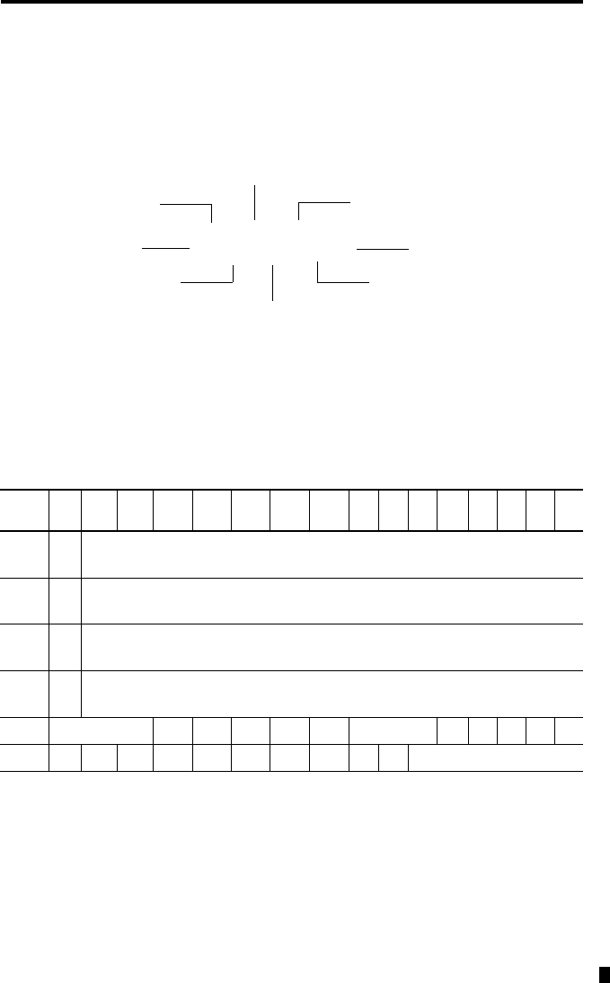
The addressing scheme for 1762 Expansion I/O is shown below.
(1) I/O located on the controller (embedded I/O) is slot 0. I/O added to the controller (expansion I/O) begins with slot 1.
Input Data File
For each module, slot x, words 0…3 contain the analog values of the inputs. The input data file is
shown below.
Word/
Bit
15 14 13 12 11 10 9 8 7 6 5 4 3
2 1 0
0
SGN
Analog Input Data Channel 0
1
SGN
Analog Input Data Channel 1
2
SGN
Analog Input Data Channel 2
3
SGN
Analog Input Data Channel 3
4 Reserved OC4 OC3 OC2 OC1 OC0 Reserved S4 S3 S2 S1 S0
5 U0 O0 U1 O1 U2 O2 U3 O3 U4 O4 Reserved
I1:x.0/0
File Type = Input (I)
Data File
0 or 1
Slot Number
(1)
Word
Bit
Bit Delimiter
Word Delimiter
Slot Delimiter
Data File # 0 = Output
Data File # 1 = Input