Installation Instructions MicroLogix 1200 Thermocouple/mV Input Module Catalog Number 1762-IT4 Table of Contents Topic Page Module Overview 2 Description 3 Module Installation 4 System Assembly 5 Mounting 6 Field Wiring Connections 8 Cold Junction Compensation (CJC) 12 I/O Memory Mapping 13 Specifications 16 North American Hazardous Location Approval 21 Additional Resources 22 Publication 1762-IN013B-EN-P - June 2013
MicroLogix 1200 Thermocouple/mV Input Module Module Overview The thermocouple/mV modules receive and store digitally converted thermocouple and/or millivolt (mV) analog data from any combination of up to four thermocouple or millivolt analog sensors. Each input channel is individually configurable via software for a specific input device and provides open-circuit, over-range and under-range detection and indication. The module receives all of its +5V DC and +24V DC power from the 1762 expansion I/O bus.
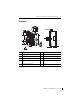
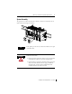
MicroLogix 1200 Thermocouple/mV Input Module 3 Description 9 1a 1a 7 3 6 6 5 2 1b 4 8 2 1b Item Description Item Description 1a upper panel mounting tab 5 bus connector cover 1b lower panel mounting tab 6 flat ribbon cable with bus connector (female) 2 power diagnostic LED 7 terminal block 3 module door with terminal identification label 8 DIN rail latch 4 bus connector with male pins 9 pull loop Publication 1762-IN013B-EN-P - June 2013
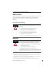
MicroLogix 1200 Thermocouple/mV Input Module Module Installation 1762 I/O is suitable for use in an industrial environment when installed in accordance with these instructions. Specifically, this equipment is intended for use in clean, dry environments (Pollution degree 2(1)) and to circuits not exceeding Over Voltage Category II(2) (IEC 60664-1).(3) Prevent Electrostatic Discharge ATTENTION Electrostatic discharge can damage integrated circuits or semiconductors if you touch bus connector pins.
MicroLogix 1200 Thermocouple/mV Input Module 5 System Assembly The expansion I/O module is attached to the controller or another I/O module by means of a ribbon cable after mounting as shown below. TIP WARNING Use the pull loop on the connector to disconnect modules. Do not pull on the ribbon cable. EXPLOSION HAZARD • In Class I, Division 2 applications, the bus connector must be fully seated and the bus connector cover must be snapped in place.
MicroLogix 1200 Thermocouple/mV Input Module Mounting ATTENTION Do not remove protective debris strip until after the module and all other equipment near the module is mounted and wiring is complete. Once wiring is complete and the module is free of debris, carefully remove protective debris strip. Failure to remove strip before operating can cause overheating.
MicroLogix 1200 Thermocouple/mV Input Module 7 DIN Rail Mounting The module can be mounted using the following DIN rails: 35 x 7.5 mm (EN 50 022 - 35 x 7.5) or 35 x 15 mm (EN 50 022 - 35 x 15). Before mounting the module on a DIN rail, close the DIN rail latch. Press the DIN rail mounting area of the module against the DIN rail. The latch will momentarily open and lock into place.
MicroLogix 1200 Thermocouple/mV Input Module Field Wiring Connections Grounding the Module This product is intended to be mounted to a well-grounded mounting surface such as a metal panel. Additional grounding connections from the module’s mounting tabs or DIN rail, are not required unless the mounting surface cannot be grounded. Refer to Industrial Automation Wiring and Grounding Guidelines, Allen-Bradley publication 1770-4.1, for additional information.
MicroLogix 1200 Thermocouple/mV Input Module 9 • Ground the shield drain wire at one end only. The typical location is the same point as the sensor ground reference. – For grounded thermocouples or millivolt sensors, this is at the sensor end. – For insulated/ungrounded thermocouples, this is at the module end. Contact your sensor manufacturer for additional details. • If it is necessary to connect the shield drain at the module end, connect it to earth ground using a panel or DIN rail mounting screw.
MicroLogix 1200 Thermocouple/mV Input Module Wiring the Finger-Safe Terminal Block ATTENTION Be careful when stripping wires. Wire fragments that fall into a module could cause damage when power is applied. Once wiring is complete, ensure the module is free of all metal fragments. When wiring the terminal block, keep the finger-safe cover in place. 1. Route the wire under the terminal pressure plate. You can use the stripped end of the wire or a spade lug. The terminals will accept a 6.35 mm (0.
MicroLogix 1200 Thermocouple/mV Input Module 11 Wiring Input Devices to the 1762-IT4 ATTENTION Be careful when stripping wires. Wire fragments that fall into a module could cause damage at power up. Once wiring is complete, ensure the module is free of all metal fragments.
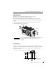
MicroLogix 1200 Thermocouple/mV Input Module Terminal Block with CJC Sensor and Thermocouple Junctions CJC sensor CJC+ IN 0+ + grounded thermocouple IN 0- + CJC IN 2+ - ungrounded thermocouple IN 1 + IMPORTANT within 10V DC IN 1- IN 2- + IN 3+ IN 3- TIP - - grounded thermocouple When using an ungrounded thermocouple, the shield must be connected to ground at the module end.
MicroLogix 1200 Thermocouple/mV Input Module 13 I/O Memory Mapping Addressing The addressing scheme for 1762 Expansion I/O is shown below. Slot Number (1) Data File 0 or 1 Word File Type = Input (I) Slot Delimiter I1:x.0/0 Bit Bit Delimiter Data File # 0 = Output Data File # 1 = Input Word Delimiter (1) I/O located on the controller (embedded I/O) is slot 0. I/O added to the controller (expansion I/O) begins with slot 1.
MicroLogix 1200 Thermocouple/mV Input Module The bits are defined as follows: • Sx = General status bits for channels 0…3 (S0 …S3) and the CJC sensor (S4). This bit is set (1) when an error (over-range, under-range, open-circuit, or input data not valid) exists for that channel. An input data not valid condition is determined by the user program. Refer to the MicroLogix 1200 I/O Thermocouple/mV Input Module User Manual, publication number 1762-UM002 for additional details.
MicroLogix 1200 Thermocouple/mV Input Module Enable Channel Data Format (1) Make these bit settings 15 14 13 12 11 10 9 8 7 6 5 10 Hz 60 Hz 50 Hz 250Hz 500 Hz 1 kHz Upscale Downscale Hold Last State Zero Degrees C 0 Degrees F 1 0 0 1 1 Thermocouple J Thermocouple K Thermocouple T Thermocouple E Thermocouple R Thermocouple S Thermocouple B Thermocouple N Thermocouple C -50…50 mV -100…100 mV Raw/Proportional Engineering Units Engineering UnitsX10 Scaled-for-PID Percent Range Disable 0 Enable 0 0 0 0
MicroLogix 1200 Thermocouple/mV Input Module Module Configuration Word Word 4 of the configuration data file contains the Enable/Disable Cyclic Calibration bit as shown in the table below. To Select Cyclic Calibration (1) Make these bit settings 15 14 13 12 11 10 9 8 7 6 5 4 3 2 1 (1) Enabled Disabled 1 When enabled, an autocalibration cycle is performed on all enabled channels every 5 minutes.
MicroLogix 1200 Thermocouple/mV Input Module 17 Input Specifications Specification 1762-IT4 Number of Inputs 4 input channels plus a CJC sensor Resolution 15 bits plus sign Bus Current Draw, max 40 mA @ 5V DC 50 mA @ 24V DC Heat Dissipation 1.5 Total Watts (The Watts per point, plus the minimum Watts, with all points energized.) Converter Type Delta Sigma Input Filtering Programmable notch filter with 10, 50, 60, 250, 500 and 1k Hz frequencies.
MicroLogix 1200 Thermocouple/mV Input Module (1) Rated working voltage is the maximum continuous voltage that can be applied at the input terminal, including the input signal and the value that floats above ground potential (for example, 30V DC input signal and 20V DC potential above ground). (2) For proper operation, both the plus and minus input terminals must be within ±10V DC of analog common.
MicroLogix 1200 Thermocouple/mV Input Module 19 Channel Update Time Filter Frequency Selection Channel Update Time 10 Hz 303 ms 50 Hz 63 ms 60 Hz 53 ms 250 Hz 15 ms 500 Hz 9 ms 1 kHz 7 ms Repeatability Input Type Repeatability for 10 Hz Filter at 25°C [77°F] Themocouple J ±0.1 °C [±0.18 °F] Themocouple N (-110…1300 °C [-166…2372 °F]) ±0.1 °C [±0.18 °F] Themocouple N (-210…-110 °C [-346…-166 °F]) ±0.25 °C [±0.45 °F] Themocouple T (-170…400 °C [-274…752 °F]) ±0 .1 °C [±0.
MicroLogix 1200 Thermocouple/mV Input Module Certifications Certification (when product is Value marked)(1) c-UL-us UL Listed Industrial Control Equipment, certified for US and Canada. UL Listed for Class I, Division 2 Group A,B,C,D Hazardous Locations, certified for U.S and Canada. See UL File E334470. CE European Union 2004/108/EC EMC Directive, compliant with: EN 61326-1; Meas./Control/Lab.
MicroLogix 1200 Thermocouple/mV Input Module 21 North American Hazardous Location Approval This equipment is suitable for use in Class I, Division 2, Groups A, B, C, D or non-hazardous locations only. The following WARNING statement applies to use in hazardous locations.
MicroLogix 1200 Thermocouple/mV Input Module Additional Resources Publication Description MicroLogix 1200 Programmable Controllers User Manual, Information on installing, wiring, and operating a publication 1762-UM001. MicroLogix 1200 Programmable Controller. MicroLogix 1200 Programmable Controllers Installation Instructions publication 1762-IN006. Installation guide for the MicroLogix 1200 Programmable Controller.
MicroLogix 1200 Thermocouple/mV Input Module 23 Notes: Publication 1762-IN013B-EN-P - June 2013
Rockwell Automation Support Rockwell Automation provides technical information on the Web to assist you in using its products. At http://www.rockwellautomation.com/support/, you can find technical manuals, a knowledge base of FAQs, technical and application notes, sample code and links to software service packs, and a MySupport feature that you can customize to make the best use of these tools.