
Owner manual


Publication 1762-UM003A-EN-P - February 2003
Diagnostics and Troubleshooting 4-5
Module Error Definition
Table
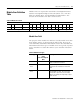
Module errors are expressed in two fields as four-digit Hex format
with the most significant digit as irrelevant (“don’t care”). The two
fields are “Module Error” and “Extended Error Information”. The
structure of the module error data is shown below.
Module Error Field
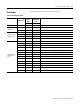
The purpose of the module error field is to classify module errors into
three distinct groups, as described in the table below. The type of
error determines what kind of information exists in the extended error
information field. These types of module errors are typically reported
in the controller’s I/O status file. Refer to your controller manual for
details.
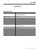
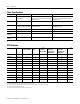
Table 4.1 Module Error Table
“Don’t Care” Bits Module Error Extended Error Information
1514 13 12 11109876543210
00 0 0 000000000000
Hex Digit 4 Hex Digit 3 Hex Digit 2 Hex Digit 1
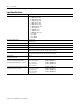
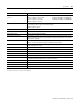
Table 4.2 Module Error Types
Error Type Module Error Field
Value
Bits 11 through 09
(Bin)
Description
No Errors 000 No error is present. The extended error field
holds no additional information.
Hardware
Errors
001 General and specific hardware error codes are
specified in the extended error information
field.
Configuration
Errors
010 Module-specific error codes are indicated in
the extended error field. These error codes
correspond to options that you can change
directly. For example, the input range or input
filter selection.