
Owner manual

Publication 1762-UM003A-EN-P - February 2003
3-8 Module Data, Status, and Channel Configuration
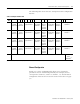
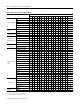
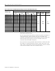
Table 3.4 Channel Configuration Bit Definitions
To Select Make these bit settings
1514131211109876543210
Decimals
Filter Frequency
10 Hz
110 6
60 Hz
000 0
50 Hz
001 1
250Hz
011 3
500 Hz
100 4
1 kHz
101 5
Excitation
Current
1.0 mA
0 0
0.5 mA
1 8
Cyclic Lead
Compensation
Enable
0 0
Disable
1 16
Open/Broken
Circuit Response
Upscale
00 0
Downscale
01 32
Last State
10 64
Zero
11 96
Temperature
Units/Mode
(1)
°C 0 0
°F
1 128
Input/Sensor
Type
100Ω Platinum 385
0000 0
200Ω Platinum 385
0001 256
500Ω Platinum 385
0010 512
1000Ω Platinum 385
(2)
0011 768
100Ω Platinum 3916
0100 1024
200Ω Platinum 3916
0101 1280
500Ω Platinum 3916
0110 1536
1000Ω Platinum 3916
(2)
0111 1792
10 Copper 426
(3)
1000 2048
120 Nickel 618
1001 2304
120 Nickel 672
1010 2560
604 Nickel-Iron 518
1011 2846
150 Ω
1100 3072
500 Ω
1101 3328
1000 Ω
1110 3584
3000Ω
(2)
1111 3840
Data Format
Raw/Proportional
000 0
Engineering Units
001 4096
Engr. Units X 10
100 16384
Scaled-for-PID
010 8192
Percent Range
011 12288
Enable/Disable
Channel
Enable 1
-32768
Disable 0
0
(1) Ignored for a resistance device input.
(2) Valid only with the 0.5 mA excitation current.
(3) Valid only with the 1.0 mA excitation current.