
Owner manual


Publication 1762-UM003A-EN-P - February 2003
Module Data, Status, and Channel Configuration 3-3
Input Data File
The input data table allows you to access RTD input module read data
for use in the control program, via word and bit access. The data table
structure is shown in table below.
Input Data Values
Data words 0 through 3 correspond to channels 0 through 3 and
contain the converted analog input data from the input device.
General Status Flag Bits (S0 to S3)
Bits S0 through S3 of Word 3 contain the general status information for
channels 0 through 3, respectively. This bit is set (1) when an error
(over- or under-range, short-circuit, open-circuit, or input data not
valid) exists for that channel. The error conditions of the General
Status bits are logically ORed. Therefore, the user control program
determines which condition is setting the general status bit by viewing
the following bits: open-circuit, over-range, or under-range. The data
not valid condition is described on the following page.
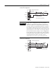
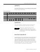
Table 3.1 Input Data Table
Word/Bit1514131211109876543210
0 RTD/Resistance Input Data Channel 0
1 RTD/Resistance Input Data Channel 1
2 RTD/Resistance Input Data Channel 2
3 RTD/Resistance Input Data Channel 3
4 Reserved OC3 OC2 OC1 OC0 Reserved S3 S2 S1 S0
5 U0 O0U1O1U2O2U3O3 Reserved
TIP
Status bits for a particular channel reflect the
configuration settings for that channel. To receive
valid status, the channel must be enabled and the
module must have stored a valid configuration word
for that channel.