
Owner manual


Publication 1762-UM003A-EN-P - February 2003
2-8 Installation and Wiring
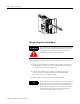
Field Wiring Connections
System Wiring Guidelines
Consider the following when wiring your system:
General
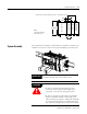
• This product is intended to be mounted to a well-grounded
mounting surface such as a metal panel. Additional grounding
connections from the module’s mounting tabs or DIN rail (if
used) are not required unless the mounting surface cannot be
grounded.
• Channels are isolated from one another by ±10V dc maximum.
• Do not use the modules NC terminals as connection points.
• Route field wiring away from any other wiring and as far as
possible from sources of electrical noise, such as motors,
transformers, contactors, and ac devices. As a general rule, allow
at least 15.2 cm (6 in.) of separation for every 120V of power.
• Routing field wiring in a grounded conduit can reduce electrical
noise.
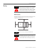
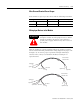
• If field wiring must cross ac or power cables, ensure that they
cross at right angles.
• To ensure optimum accuracy, limit overall cable impedance by
keeping your cable as short as possible. Locate the I/O system
as close to your sensors or actuators as your application will
permit.
• Tighten terminal screws with care. Excessive tightening can strip
a screw.
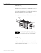
Shield Grounding
• Use Belden shielded, twisted-pair wire to ensure proper
operation and high immunity to electrical noise. Refer to the
following table and the RTD Wiring Considerations below.
• Under normal conditions, the drain wire and shield junction
should be connected to earth ground, via a panel or DIN rail
mounting screw at the 1762-IR4 module end.
Configuration
Recommended Cable
(1)
2-wire Belden™ 9501 or equivalent
3-wire
less than 30.48 m (100ft.)
Belden™ 9533 or equivalent
3-wire
greater than 30.48 m (100 ft.) or high
humidity conditions
Belden™ 83503 or equivalent
(1) For additional information, see page A-4.