Installation Instructions DC-Input/Relay-Output Combination Module Catalog Number 1762-IQ8OW6 Table of Contents For See Page Important User Information 2 Overview 3 North American Hazardous Location Approval 4 Module Description 5 Install the DC-Input/Relay-Output Combination Module 6 Mount the Module on a DIN Rail 6 Mount the Module on a Panel 7 Wire the DC-Input/Relay-Output Combination Module 8 Ground the DC-Input/Relay-Output Combination Module 9 Wire the Finger-safe Terminal Bloc
DC-Input/Relay-Output Combination Module Important User Information Solid state equipment has operational characteristics differing from those of electromechanical equipment. Safety Guidelines for the Application, Installation and Maintenance of Solid State Controls (Publication SGI-1.1 available from your local Rockwell Automation sales office or online at http://literature.rockwellautomation.
DC-Input/Relay-Output Combination Module 3 Overview The 1762 I/O is suitable for use in an industrial environment when installed in accordance with these instructions. Specifically, this equipment is intended for use in clean, dry environments (Pollution degree 2(1)) and to circuits not exceeding Over Voltage Category II(2) (IEC 60664-1).(3). Prevent Electrostatic Discharge ATTENTION Electrostatic discharge can damage integrated circuits or semiconductors if you touch bus connector pins.
DC-Input/Relay-Output Combination Module North American Hazardous Location Approval The following modules are North American Hazardous Location approved: 1762-IQ8OW6 The following information applies when operating this equipment in hazardous locations: Informations sur l’utilisation de cet équipement en environnements dangereux: Products marked "CL I, DIV 2, GP A, B, C, D" are suitable for use in Class I Division 2 Groups A, B, C, D, Hazardous Locations and nonhazardous locations only.
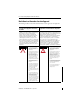
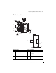
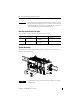
DC-Input/Relay-Output Combination Module 5 Module Description 9 1a 3 7 6 5 1b 4 1a 6 2 8 Item Description Item Description 1a upper panel mounting tab 5 bus connector cover 1b lower panel mounting tab 6 flat ribbon cable with bus connector (female pins) 2 I/O diagnostic LEDs 7 terminal block 3 module door with terminal identification label 8 DIN rail latch 4 bus connector with male pins pull loop 9 1b Publication 1762-IN018B-EN-P - July 2013
DC-Input/Relay-Output Combination Module Install the DC-Input/Relay-Output Combination Module ATTENTION Do not remove protective debris strip until after the module and all other equipment near the module is mounted and wiring is complete. Once wiring is complete and the module is free of debris, carefully remove protective debris strip. Failure to remove strip before operating can cause overheating.
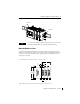
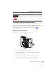
DC-Input/Relay-Output Combination Module 7 End Anchor End Anchor TIP For environments with greater vibration and shock concerns, use the panel mounting method described below, instead of DIN-rail mounting. Mount the Module on a Panel Use the dimensional template shown below to mount the module. The preferred mounting method is to use two M4 or #8 panhead screws per module. M3.5 or #6 panhead screws may also be used, but a washer may be needed to ensure a good ground contact.
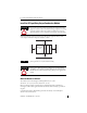
DC-Input/Relay-Output Combination Module Wire the DC-Input/Relay-Output Combination Module Basic wiring of inputs(1) and outputs(2) is shown below. +DC (Sinking) -DC (Sourcing) IN 0 IN 1 IN 2 IN 3 +DC (Sinking) -DC (Sourcing) IN 4 -DC (Sinking) +DC (Sourcing) DC COM 0 IN 5 IN 6 IN 7 DC COM 1 -DC (Sinking) +DC (Sourcing) VAC VDC L1 or +DC OUT 0 CR Connected Internally VAC VDC L1 or +DC OUT 1 CR OUT 3 CR OUT 5 CR L2 or -DC OUT 2 OUT 4 A write-on label is provided with the module.
DC-Input/Relay-Output Combination Module 9 ATTENTION Miswiring of the module to an AC power source will damage the module. Ground the DC-Input/Relay-Output Combination Module This product is intended to be mounted to a well-grounded mounting surface such as a metal panel. Additional grounding connections from the module’s mounting tabs or DIN rail (if used) are not required unless the mounting surface cannot be grounded.
DC-Input/Relay-Output Combination Module TIP If you need to remove the finger-safe cover, insert a screw driver into one of the square wiring holes and gently pry the cover off. If you wire the terminal block with the finger-safe cover removed, you will not be able to put it back on the terminal block because the wires will be in the way.
DC-Input/Relay-Output Combination Module 11 EXPLOSION HAZARD ATTENTION • In Class I, Division 2 applications, the bus connector must be fully seated and the bus connector cover must be snapped in place. • In Class I, Division 2 applications, all modules must be mounted in direct contact with each other as shown on page 6. If DIN-rail mounting is used, an end stop must be installed ahead of the controller and after the last 1762 I/O module.
DC-Input/Relay-Output Combination Module Output Memory Map Word For each output module, the output data file contains the controller-directed state of the digital output points. Bit positions 0…15 correspond to output terminals 0…15.
DC-Input/Relay-Output Combination Module 13 Specifications Input Specifications Specification Value Voltage Category 24V DC (Sink/Source)(1) Operating Voltage Range 10…30V DC @ 30 °C (86 °F) 10…26.4V DC @ 65 °C (149 °F) Number of Inputs 8 On-state Voltage, (Min) 10V DC Off-state Voltage, (Max) 5V DC On-state Current, (Min) 2.0 mA Off-state Current, (Max) 1.
DC-Input/Relay-Output Combination Module Output Specifications Specification Value Voltage Range 5…265V AC 5…125V DC Commons per Module 6 Output Type 6-Form A (normally open) Signal Delay Time On-delay: 10 mS (max) Off-delay: 10 mS (max) Off Leakage Current 0 mA On-state Current (Min.) 10 mA @ 5V DC Continuous Current per Point See table on page 14. Continuous Current per Module 8A Total Controlled Load 1440VA/Module max Relay Contact Ratings Volts (max.
DC-Input/Relay-Output Combination Module 15 General Specifications Specification Value Dimensions, HxWxD 90 x 40.4 x 87 (3.54 x 1.59 x 3.43 in.) height including mounting tabs is 110 mm (4.33in.) Approximate Shipping Weight (with carton) 280g (0.62 lbs.) Bus Current Draw, (Max) 110 mA @ 5V DC 80 mA @ 24V DC Heat Dissipation 5.0 W @ 30V DC 4.4 W @ 26.4V DC (The Watts per point, plus the minimum W, with all points energized.
DC-Input/Relay-Output Combination Module Environmental Specifications Specification Value Operation Temperature Range -20…+65 °C (-4…+149 °F) Storage Temperature Range -40…+85 °C (-40…+185 °F) Operating Humidity 5…95% non-condensing Operating Altitude 2000 m (6561 ft) Certifications Certification (when Value product is marked)(1) c-UL-us UL Listed Industrial Control Equipment, certified for US and Canada. UL Listed for Class I, Division 2 Group A,B,C,D Hazardous Locations, certified for U.
DC-Input/Relay-Output Combination Module 17 Additional Resources Refer to For More Information on this Topic MicroLogix 1200 Programmable Controllers User Manual (Bulletin 1762 Controllers and Expansion I/O), publication 1762-UM001. Information on installing, wiring, and operating a MicroLogix 1200 programmable controller system MicroLogix 1200 Programmable Controllers Installation Instructions, publication 1762-IN006. Installation guide for the MicroLogix 1200 programmable controller.
DC-Input/Relay-Output Combination Module Notes: Publication 1762-IN018B-EN-P - July 2013
DC-Input/Relay-Output Combination Module 19 Notes: Publication 1762-IN018B-EN-P - July 2013
Rockwell Automation Support Rockwell Automation provides technical information on the Web to assist you in using its products. At http://www.rockwellautomation.com/support/, you can find technical manuals, a knowledge base of FAQs, technical and application notes, sample code and links to software service packs, and a MySupport feature that you can customize to make the best use of these tools.