Installation Instructions MicroLogix 1762-IQ16 DC Input Module Catalog Number 1762-IQ16 Table of Contents Topic Page Important User Information 2 North American Hazardous Location Approval 4 Additional Resources 5 Overview 6 Module Description 7 Mount the Module 8 Field Wiring Connections 11 Grounding the Module 11 Wiring the Finger-Safe Terminal Block 13 I/O Memory Mapping 14 Specifications 15
MicroLogix 1762-IQ16 DC Input Module Important User Information Solid state equipment has operational characteristics differing from those of electromechanical equipment. Safety Guidelines for the Application, Installation and Maintenance of Solid State Controls (Publication SGI-1.1 available from your local Rockwell Automation sales office or online at http://literature.rockwellautomation.com) describes some important differences between solid state equipment and hard-wired electromechanical devices.
MicroLogix 1762-IQ16 DC Input Module 3 Environment and Enclosure ATTENTION This equipment is intended for use in a Pollution Degree 2 industrial environment, in overvoltage Category II applications (as defined in IEC 60664-1), at altitudes up to 2000 m (6562 ft) without derating.This equipment is considered Group 1, Class A industrial equipment according to IEC/CISPR 11.
MicroLogix 1762-IQ16 DC Input Module North American Hazardous Location Approval The following modules are North American Hazardous Location approved: 1762-IQ16 The following information applies when operating this equipment in hazardous locations: Informations sur l’utilisation de cet équipement en environnements dangereux: Products marked "CL I, DIV 2, GP A, B, C, D" are suitable for use in Class I Division 2 Groups A, B, C, D, Hazardous Locations and nonhazardous locations only.
MicroLogix 1762-IQ16 DC Input Module 5 Additional Resources Resource Description MicroLogix 1100 Programmable Controllers User Manual, publication 1763-UM001. A more detailed description of how to install and use your MicroLogix 1100 programmable controller and expansion I/O system. MicroLogix 1200 Programmable Controllers User Manual, publication 1762-UM001. A more detailed description of how to install and use your MicroLogix 1200 programmable controller and expansion I/O system.
MicroLogix 1762-IQ16 DC Input Module Overview The 1762 input module is suitable for use in an industrial environment when installed in accordance with these instructions. Specifically, this equipment is intended for use in clean, dry environments (Pollution degree 2(1)) and to circuits not exceeding Over Voltage Category II(2) (IEC 60664-1)(3). Install your module using these installation instructions.
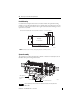
MicroLogix 1762-IQ16 DC Input Module 7 Module Description 5 1a 1a 2 9 6 4 4 2 7 3 3 1b 8 45164 2 45165 This equipment is sensitive to electrostatic discharge (ESD). Follow ESD prevention guidelines when handling this equipment.
MicroLogix 1762-IQ16 DC Input Module Mount the Module General Considerations Most applications require installation in an industrial enclosure to reduce the effects of electrical interference and environmental exposure. Locate your controller as far as possible from power lines, load lines, and other sources of electrical noise such as hard-contact switches, relays, and AC motor drives.
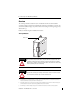
MicroLogix 1762-IQ16 DC Input Module 9 Module Spacing Maintain spacing from objects such as enclosure walls, wireways and adjacent equipment. Allow 50.8 mm (2 in.) of space on all sides for adequate ventilation, as shown: 1762 I/O 1762 I/O Side MicroLogix 1100/1200/1400 1762 I/O Top Side Bottom 44913 DIN Rail Mounting The module can be mounted using the following DIN rails: 35 x 7.5 mm (EN 50 022 - 35 x 7.5) or 35 x 15 mm (EN 50 022 - 35 x 15).
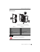
MicroLogix 1762-IQ16 DC Input Module Panel Mounting Use the dimensional template shown below to mount the module. The preferred mounting method is to use two M4 (#8) panhead screws per module. M3.5 (#6) panhead screws may also be used, but a washer may be needed to ensure a good mechanical contact. Mounting screws are required on every module. For more than two I/O modules: measure (number of modules - 1) x 40 mm (1.59 in.) 95 (3.74) 40.4 (1.59) 1762 I/O MicroLogix 1100/1200/1400 1762 I/O 100.
MicroLogix 1762-IQ16 DC Input Module 11 Field Wiring Connections Grounding the Module In solid-state control systems, grounding and wire routing helps limit the effects of noise due to electromagnetic interference (EMI). Run the ground connection from the ground screw of the controller to the ground bus prior to connecting any devices. Use AWG #14 wire. For AC-powered controllers, this connection must be made for safety purposes.
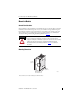
MicroLogix 1762-IQ16 DC Input Module Input Wiring Basic wiring of input devices to the 1762-IQ16 is shown below.
MicroLogix 1762-IQ16 DC Input Module 13 Wiring the Finger-Safe Terminal Block TIP Finger-safe cover not shown for clarity. When wiring the terminal block, keep the finger-safe cover in place. 1. Route the wire under the terminal pressure plate. You can use the stripped end of the wire or a spade lug. The terminals will accept a 6.35 mm (0.25 in.) spade lug. 2. Tighten the terminal screw making sure the pressure plate secures the wire. Recommended torque when tightening terminal screws is 0.
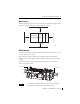
MicroLogix 1762-IQ16 DC Input Module I/O Memory Mapping Input Data File Word For each input module, the input data file contains the current state of the field input points. Bit positions 0…15 correspond to input terminals 0…15. Bit Position 15 14 13 12 11 10 9 8 7 6 5 4 3 2 1 0 0 r r r r r r r r r r r r r r r r r = read only 1762 Expansion I/O Addressing The addressing scheme for 1762 Expansion I/O is shown below.
MicroLogix 1762-IQ16 DC Input Module 15 Specifications General Attribute Value Dimensions, HxWxD 90 x 40.4 x 87 mm (3.54 x 1.59 x 3.43 in.) Shipping weight, approx. 230g (8.11oz) See Wire Size and Terminal Screw Torque on page 13 Wire size (1) Wiring category 2 - on signal ports Pilot duty rating Not rated Enclosure type rating IP20 North American temp code T3C (1) Use this Conductor Category information for planning conductor routing.
MicroLogix 1762-IQ16 DC Input Module Input Attribute Value Vendor I.D. Code 1 Product type code 7 Product code 97 (1) Sinking/Sourcing Inputs - Sourcing/sinking describes the current flow between the I/O module and the field device. Sourcing I/O circuits supply (source) current to sinking field devices. Sinking I/O circuits are driven by a current sourcing field device. Field devices connected to the negative side (DC Common) of the field power supply are sinking field devices.
MicroLogix 1762-IQ16 DC Input Module 17 Environmental Attribute Value EFT/B immunity IEC 61000-4-4: ±2 kV at 5 kHz on signal ports Surge transient immunity IEC 61000-4-5: ±1 kV line-line(DM) and ±2 kV line-earth(CM) on signal ports Conducted RF immunity IEC 61000-4-6: 10V rms with 1 kHz sine-wave 80% AM from 150 kHz...
MicroLogix 1762-IQ16 DC Input Module Certifications Certification (when Value product is marked)(1) c-UL-us UL Listed Industrial Control Equipment, certified for US and Canada. See UL File E322657. UL Listed for Class I, Division 2 Group A,B,C,D Hazardous Locations, certified for U.S. and Canada. See UL File E334470. CE European Union 2004/108/EC EMC Directive, compliant with: EN 61326-1; Meas./Control/Lab.
MicroLogix 1762-IQ16 DC Input Module 19 Notes: Publication 1762-IN010C-EN-P - June 2013
Rockwell Automation Support Rockwell Automation provides technical information on the Web to assist you in using its products. At http://www.rockwellautomation.com/support/, you can find technical manuals, a knowledge base of FAQs, technical and application notes, sample code and links to software service packs, and a MySupport feature that you can customize to make the best use of these tools.