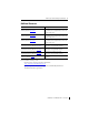
Installation Instructions MicroLogix 1762-IF4 Analog Input Module Catalog Number 1762-IF4 Table of Contents Topic Page Important User Information 2 North American Hazardous Location Approval 4 Additional Resources 5 Overview 6 Module Description 7 Mount the Module 8 Field Wiring Connections 11 Input Type Selection 12 Wiring the Finger-Safe Terminal Block 15 Wire Size and Terminal Screw Torque 15 Specifications 20
MicroLogix 1762-IF4 Analog Input Module Important User Information Solid state equipment has operational characteristics differing from those of electromechanical equipment. Safety Guidelines for the Application, Installation and Maintenance of Solid State Controls (Publication SGI-1.1 available from your local Rockwell Automation sales office or online at http://literature.rockwellautomation.
MicroLogix 1762-IF4 Analog Input Module 3 Environment and Enclosure ATTENTION This equipment is intended for use in a Pollution Degree 2 industrial environment, in overvoltage Category II applications (as defined in IEC 60664-1), at altitudes up to 2000 m (6562 ft) without derating.This equipment is considered Group 1, Class A industrial equipment according to IEC/CISPR 11.
MicroLogix 1762-IF4 Analog Input Module North American Hazardous Location Approval The following modules are North American Hazardous Location approved: 1762-IF4 The following information applies when operating this equipment in hazardous locations: Informations sur l’utilisation de cet équipement en environnements dangereux: Products marked "CL I, DIV 2, GP A, B, C, D" are suitable for use in Class I Division 2 Groups A, B, C, D, Hazardous Locations and nonhazardous locations only.
MicroLogix 1762-IF4 Analog Input Module 5 Additional Resources Resource Description MicroLogix 1100 Programmable Controllers User Manual, publication 1763-UM001. A more detailed description of how to install and use your MicroLogix 1100 programmable controller and expansion I/O system. MicroLogix 1200 Programmable Controllers User Manual, publication 1762-UM001. A more detailed description of how to install and use your MicroLogix 1200 programmable controller and expansion I/O system.
MicroLogix 1762-IF4 Analog Input Module Overview The 1762 input module is suitable for use in an industrial environment when installed in accordance with these instructions. Specifically, this equipment is intended for use in clean, dry environments (Pollution degree 2(1)) and to circuits not exceeding Over Voltage Category II(2) (IEC 60664-1)(3). Install your module using these installation instructions.
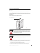
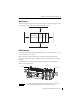
MicroLogix 1762-IF4 Analog Input Module 7 Module Description 5 6 1a 1a 10 7 3 2 3 8 4 4 1b Front view Left side view 45156 9 45157 This equipment is sensitive to electrostatic discharge (ESD). Follow ESD prevention guidelines when handling this equipment.
MicroLogix 1762-IF4 Analog Input Module Mount the Module General Considerations Most applications require installation in an industrial enclosure to reduce the effects of electrical interference and environmental exposure. Locate your controller as far as possible from power lines, load lines, and other sources of electrical noise such as hard-contact switches, relays, and AC motor drives.
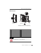
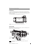
MicroLogix 1762-IF4 Analog Input Module 9 Module Spacing Maintain spacing from objects such as enclosure walls, wireways and adjacent equipment. Allow 50.8 mm (2 in.) of space on all sides for adequate ventilation, as shown: 1762 I/O 1762 I/O Side MicroLogix 1100/1200/1400 1762 I/O Top Side Bottom 44913 DIN Rail Mounting The module can be mounted using the following DIN rails: 35 x 7.5 mm (EN 50 022 - 35 x 7.5) or 35 x 15 mm (EN 50 022 - 35 x 15).
MicroLogix 1762-IF4 Analog Input Module Panel Mounting Use the dimensional template shown below to mount the module. The preferred mounting method is to use two M4 (#8) panhead screws per module. M3.5 (#6) panhead screws may also be used, but a washer may be needed to ensure a good mechanical contact. Mounting screws are required on every module. For more than two I/O modules: measure (number of modules - 1) x 40 mm (1.59 in.) 95 (3.74) 40.4 (1.59) 1762 I/O MicroLogix 1100/1200/1400 1762 I/O 100.
MicroLogix 1762-IF4 Analog Input Module 11 Field Wiring Connections Grounding the Module In solid-state control systems, grounding and wire routing helps limit the effects of noise due to electromagnetic interference (EMI). Run the ground connection from the ground screw of the controller to the ground bus prior to connecting any devices. Use AWG #14 wire. For AC-powered controllers, this connection must be made for safety purposes.
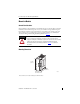
MicroLogix 1762-IF4 Analog Input Module Input Type Selection Select the input type, current or voltage, using the switch located on the module’s circuit board and the input type/range selection bits in the Configuration Data File (see page 17). You can access the switch through the ventilation slots on the top of the module. The factory default setting for all switches is Current. Switch positions are shown below.
MicroLogix 1762-IF4 Analog Input Module 13 Basic Input Wiring to the 1762-IF4 Module Differential Sensor Transmitter Types IN 0 (+) Analog Sensor IN 0 (-) IN 1 (+) IN 1 (-) IN 2 (+) IN 2 (-) IN 3 (+) IN 3 (-) COM COM TIP Grounding the cable shield at the module end only usually provides sufficient noise immunity. However, for best cable shield performance, earth ground the shield at both ends, using a 0.01µF capacitor at one end to block AC power ground currents, if necessary.
MicroLogix 1762-IF4 Analog Input Module Sensor/Transmitter Types 2-Wire Transmitter + Supply (1) - Transmitter + Module - Power IN + IN COM 3-Wire Transmitter Power Supply(1) Transmitter Supply Signal + - Module IN + IN COM 4-Wire Transmitter Transmitter Supply Power Supply(1) + - + - Module Signal + - IN + IN COM (1) All power supplies rated N.E.C. Class 2.
MicroLogix 1762-IF4 Analog Input Module 15 Wiring the Finger-Safe Terminal Block ATTENTION Be careful when stripping wires. Wire fragments that fall into a module could cause damage when power is applied. Once wiring is complete, ensure the module is free of all metal fragments. When wiring the terminal block, keep the finger-safe cover in place. 1. Route the wire under the terminal pressure plate. You can use the stripped end of the wire or a spade lug. The terminals will accept a 6.35 mm (0.25 in.
MicroLogix 1762-IF4 Analog Input Module Labeling the Terminals A write-on label is provided with the module. Mark the identification of each terminal with permanent ink, and slide the label back into the door. 1762 Expansion I/O Addressing The addressing scheme for 1762 Expansion I/O is represented in the following figure. Data file Slot number(1) Word I1:x.0/0 Bit (0...15) Bit delimiter Input Word delimiter Slot delimiter (1) I/O located on the controller (embedded I/O) is slot 0.
MicroLogix 1762-IF4 Analog Input Module 17 The bits are defined as follows: • Sx = General status bits for channels 0…3. This bit is set when an error (over- or under-range) exists for that channel, or there is a general module hardware error. • Ox = Over-range flag bits for channels 0…3. These bits are set when the input signal is above the user-specified range. The module continues to convert data to the maximum full range value during an over-range condition.
MicroLogix 1762-IF4 Analog Input Module Data Format (Bits 14 …12) These bits indicate the format of the data as shown in the following table. Other combinations of these bits are not supported and result in an error. Bit Settings 14 Data Format 13 12 0 0 0 Raw/Proportional 0 1 0 Scaled for PID other Not Supported Type/Range Select (Bits 11…8) These bits indicate the type and range as in the following table. Other combinations of these bits are not supported and result in an error.
MicroLogix 1762-IF4 Analog Input Module 19 Error Codes The 1762-IF4 module notifies the controller of critical and non-critical errors. The module condition array word 0 contains the error codes that are generated by the module, as shown below. “Don’t Care” Bits Module Error Extended Error Information 15 14 13 12 11 10 9 8 7 6 5 4 3 2 1 0 0 0 0 0 0 0 0 0 0 0 0 0 0 0 0 0 Hex Digit 4 Hex Digit 3 Hex Digit 2 Hex Digit 1 The table below describes the module error codes.
MicroLogix 1762-IF4 Analog Input Module Specifications Input Attribute Value Number of inputs 4 differential (bipolar) A/D converter type Sigma-Delta Common mode voltage range (1) ±27V Common mode rejection(2) > 55 dB @ 50 and 60 Hz Non-linearity (in percent full scale) ±0.12% Typical overall accuracy ±0.32% full scale @ -20…65 °C (-4 °F…149 °F) ±0.
MicroLogix 1762-IF4 Analog Input Module 21 General Attribute Value Dimensions, HxWxD 90 x 40.4 x 87 mm (3.54 x 1.59 x 3.43 in.) Approximate shipping weight (with carton) 235 g (8.28 oz) Bus current draw, max 40 mA @ 5V DC 50 mA @ 24V DC Analog normal operating range Voltage: -10…10V DC Current: 4…20 mA Full scale(1) analog ranges Voltage: -10.5…10.5V DC Current: -21…21 mA Resolution 15 bits (bipolar) Repeatability(2) ±0.
MicroLogix 1762-IF4 Analog Input Module Environmental Attribute Value Temperature, operating IEC 60068-2-1 (Test Ad, Operating Cold), IEC 60068-2-2 (Test Bd, Operating Dry Heat), IEC 60068-2-14 (Test Nb, Operating Thermal Shock): -20... 65 °C (-4...
MicroLogix 1762-IF4 Analog Input Module 23 Certifications Certification (when Value product is marked)(1) c-UL-us UL Listed Industrial Control Equipment, certified for US and Canada. See UL File E322657. UL Listed for Class I, Division 2 Group A,B,C,D Hazardous Locations, certified for U.S. and Canada. See UL File E334470. CE European Union 2004/108/EC EMC Directive, compliant with: EN 61326-1; Meas./Control/Lab.
Rockwell Automation Support Rockwell Automation provides technical information on the Web to assist you in using its products. At http://www.rockwellautomation.com/support/, you can find technical manuals, a knowledge base of FAQs, technical and application notes, sample code and links to software service packs, and a MySupport feature that you can customize to make the best use of these tools.