Installation Instructions MicroLogix™ 1762-IA8 120V ac Input Module Inside Description .......................................................3 Installation........................................................4 Mounting ..........................................................5 System Assembly .............................................7 Field Wiring Connections...................................7 I/O Memory Mapping ......................................10 Specifications ............................
MicroLogix™ 1762-IA8 120V ac Input Module For More Information For Refer to this Document Information on installing, wiring, and operating a MicroLogix 1200 Programmable Controller MicroLogix 1200 Programmable 1762-UM001A-US-P Controllers User Manual Installation guide for the MicroLogix 1200 Programmable Controller. MicroLogix 1200 Programmable 1762-IN006A-ML-P Controllers Installation Instructions Installation guide for the MicroLogix 1200 Memory Module and Real Time Clock.
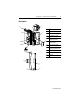
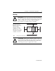
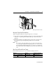
MicroLogix™ 1762-IA8 120V ac Input Module 3 Description 9 1a Item Description 7 3 1a upper panel mounting tab 1b lower panel mounting tab 2 I/O diagnostic LEDs 3 module door with terminal identification label 4 bus connector with male pins 5 bus connector cover 6 flat ribbon cable with bus connector (female pins) 7 terminal block 8 DIN rail latch 9 pull loop 5 6 1b 4 2 1a 6 2 8 1b 1762-IN002A-US-P
MicroLogix™ 1762-IA8 120V ac Input Module Installation 1762 I/O is suitable for use in an industrial environment when installed in accordance with these instructions. Specifically, this equipment is intended for use in clean, dry environments (Pollution degree 2(1)) and to circuits not exceeding Over Voltage Category II(2) (IEC 60664-1).(3) Prevent Electrostatic Discharge ! ATTENTION: Electrostatic discharge can damage integrated circuits or semiconductors if you touch bus connector pins.
MicroLogix™ 1762-IA8 120V ac Input Module 5 Mounting ! ATTENTION: Do not remove protective debris strip until after the module and all other equipment near the module is mounted and wiring is complete. Once wiring is complete and the module is free of debris, carefully remove protective debris strip. Failure to remove strip before operating can cause overheating.
MicroLogix™ 1762-IA8 120V ac Input Module DIN Rail Mounting The module can be mounted using the following DIN rails: 35 x 7.5 mm (EN 50 022 - 35 x 7.5) or 35 x 15 mm (EN 50 022 - 35 x 15). Before mounting the module on a DIN rail, close the DIN rail latch. Press the DIN rail mounting area of the module against the DIN rail. The latch will momentarily open and lock into place. Use DIN rail end anchors (Allen-Bradley part number 1492-EA35 or 1492-EAH35) for vibration or shock environments.
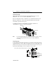
MicroLogix™ 1762-IA8 120V ac Input Module 7 System Assembly The expansion I/O module is attached to the controller or another I/O module by means of a flat ribbon cable after mounting as shown below. Note: Use the pull loop on the connector to disconnect modules. Do not pull on the ribbon cable. ATTENTION: EXPLOSION HAZARD ! • In Class I, Division 2 applications, the bus connector must be fully seated and the bus connector cover must be snapped in place.
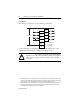
MicroLogix™ 1762-IA8 120V ac Input Module Input Wiring Basic wiring(1) of input devices to the 1762-IA8 is shown below. L1 IN 0 IN 1 IN 2 IN 3 100/120V ac IN 4 IN 5 IN 6 IN 7 L2 AC COM AC COM Commons are connected internally. A write-on label is provided with the module. Mark the identification of each terminal with permanent ink, and slide the label back into the door. ! (1) ATTENTION: Be careful when stripping wires.
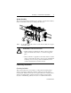
MicroLogix™ 1762-IA8 120V ac Input Module 9 Note: Finger-safe cover not shown. Wiring the Finger-Safe Terminal Block When wiring the terminal block, keep the finger-safe cover in place. 1. Route the wire under the terminal pressure plate. You can use the stripped end of the wire or a spade lug. The terminals will accept a 6.35 mm (0.25 in.) spade lug. 2. Tighten the terminal screw making sure the pressure plate secures the wire. Recommended torque when tightening terminal screws is 0.904 Nm (8 in-lbs).
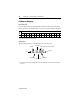
MicroLogix™ 1762-IA8 120V ac Input Module I/O Memory Mapping Input Data File For each input module, the input data file contains the current state of the field input points. Bit positions 0 through 7 correspond to input terminals 0 through 7. Word Bit Position 15 14 13 12 11 10 9 8 7 6 5 4 3 2 1 0 0 0 0 0 0 0 0 0 0 r r r r r r r r r = read only, 0 = always at a 0 or OFF state Addressing The addressing scheme for 1762 Expansion I/O is shown below.
MicroLogix™ 1762-IA8 120V ac Input Module 11 Specifications General Specifications Specification Value Dimensions 90 mm (height) x 87 mm (depth) x 40 mm (width) height including mounting tabs is 110 mm 3.543 in. (height) x 3.425 in. (depth) x 1.575 in. (width) height including mounting tabs is 4.33 in. Approximate Shipping Weight (with carton) 209 g (0.46 lbs.
MicroLogix™ 1762-IA8 120V ac Input Module Input Specifications Specification 1762-IA8 Voltage Category 100/120V ac Operating Voltage Range 79V ac to 132V ac at 47 Hz to 63 Hz Number of Inputs 8 Bus Current Draw (max.) 50 mA at 5V dc (0.25W) Heat Dissipation (max.) 2.0 Total Watts Signal Delay (max.) On Delay: 20.0 ms Off Delay: 20.0 ms Off-State Voltage (max.) 20V ac Off-State Current (max.) 2.5 mA On-State Voltage (min.) 79V ac (min.) 132V ac (max.) On-State Current 5.0 mA (min.
MicroLogix™ 1762-IA8 120V ac Input Module 13 Hazardous Location Considerations This equipment is suitable for use in Class I, Division 2, Groups A, B, C, D or non-hazardous locations only. The following ATTENTION statement applies to use in hazardous locations. ATTENTION: EXPLOSION HAZARD ! • Substitution of components may impair suitability for Class I, Division 2. • Do not replace components or disconnect equipment unless power has been switched off.
MicroLogix™ 1762-IA8 120V ac Input Module Environnements dangereux Cet équipement est conçu pour être utilisé dans des environnements de Classe I, Division 2, Groupes A, B, C, D ou non dangereux. La mise en garde suivante s’applique à une utilisation dans des environnements dangereux. ATTENTION: DANGER D’EXPLOSION ! • La substitution de composants peut rendre cet équipement impropre à une utilisation en environnement de Classe I, Division 2.
MicroLogix™ 1762-IA8 120V ac Input Module 15 1762-IN002A-US-P
MicroLogix is a trademark of Rockwell Automation. Publication 1762-IN002A-US-P - September 1999 PN 40071-070-01(A) © (1999) Rockwell International Corporation. Printed in the U.S.A.