MicroLogix™ Ethernet Interface 1761-NET-ENI and 1761-NET-ENIW User Manual
Important User Information Solid state equipment has operational characteristics differing from those of electromechanical equipment. Safety Guidelines for the Application, Installation and Maintenance of Solid State Controls (Publication SGI-1.1 available from your local Rockwell Automation sales office or online at http://www.ab.com/manuals/gi) describes some important differences between solid state equipment and hard-wired electromechanical devices.
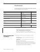
Summary of Changes The information below summarizes the changes to this manual since the last printing. To help you find new and updated information in this release of the manual, we have included change bars as shown to the right of this paragraph. Information on 1761-NET-ENI and 1761-NET-ENIW, series D, has been added throughout the manual. The table below lists the sections that document new features and additional or updated information on existing features.
2 Summary of Changes Publication 1761-UM006E-EN-P - August 2005
Table of Contents Preface Who Should Use this Manual. . . . . . . . . . . . . Purpose of this Manual . . . . . . . . . . . . . . . . . Related Documentation . . . . . . . . . . . . . . Common Techniques Used in this Manual . . . Your Questions or Comments on this Manual. . . . . . . . . . . . . . . . . . . . . . . . . . . . . . . . . . . . . . . . . . . . . . . . . . . P-1 P-1 P-2 P-2 P-3 . . . . . . . . . . . . . . . . . . . . . . . . . . . . . . . . . . . . . . . . . . . . . . . . . . . . .
iv Table of Contents Chapter 3 Operation Operation Overview . . . . . . . . . . . . . . . . . . . . . . . . . . . . . Allocation of Ethernet Connections . . . . . . . . . . . . . . . . . . ENI and ENIW Functional Overview . . . . . . . . . . . . . . . . . General Ethernet Information . . . . . . . . . . . . . . . . . . . . . . RSLinx/RSWho Connectivity Example Using ENI/ENIW Interface . . . . . . . . . . . . . . . . . . . . . . . . . . . . . . . . . . . . . .
Table of Contents v Chapter 5 Peer-to-Peer Messaging Messaging Between the ENI/ENIW and DF1 Devices . . . . . 5-1 Message to Configuration Nodes (Nodes 100 to 149) and Sending a Message to a Destination Controller (Nodes 0 to 49) . . . . 5-2 Chapter 6 EMail Messages (Node 50 to 99) Overview . . . . . . . . . . . . . . . . . . . . . Configuring Email . . . . . . . . . . . . . . . SMTP Email Address . . . . . . . . . . Destination Addresses . . . . . . . . . Message Text. . . . . . . . . . . . . . . .
vi Table of Contents Configuration Via Ladder Logic. . . . . . . . . . . . . . . . . . . 8-10 Download To The CompactLogix Controller Through Two Series A ENIs . . . . . . . . . . . . . . . . . . . . . . . . . . . . . . . . . . . . . . . 8-17 Download to the CompactLogix Controller Through a ENI/ENIW Series B/C/D via Ethernet . . . . . . . . . . . . . . . . . . . . . . . . . 8-19 Create MSG Programs for the SLC 5/05 and the ControlLogix Controllers . . . . . . . . . . . . . . . . . . . . . . . . . . . . .
Preface Read this preface to familiarize yourself with the rest of the manual. It provides information concerning: • • • • • Who Should Use this Manual who should use this manual the purpose of this manual related documentation conventions used in this manual Rockwell Automation support Use this manual if you are responsible for designing, installing, programming, or troubleshooting control systems that use Allen-Bradley Controllers on Ethernet.
Preface 2 Related Documentation The following documents contain additional information concerning Rockwell Automation products. To obtain a copy, contact your local Rockwell Automation office or distributor. For Read this Document Document Number Instructions on installing a 1761-NET-ENI or 1761-NET-ENIW Interface Converter. Ethernet Interface Installation Instructions 1761-IN007 Information on DF1 open protocol. DF1 Protocol and Command Set Reference Manual 1770-6.5.
Preface Your Questions or Comments on this Manual 3 If you find a problem with this manual, or you have any suggestions for how this manual could be made more useful to you, please contact us at the address below: Rockwell Automation Automation Control and Information Group Technical Communication, Dept. A602V P.O. Box 2086 Milwaukee, WI 53201-2086 or visit our internet page at: http://www.rockwellautomation.
Preface 4 Publication 1761-UM006E-EN-P - August 2005
Chapter 1 Product Overview This chapter gives an overview of the Ethernet Network Interface. The following topics are covered: • • • • • • • EtherNet/IP Connectivity EtherNet/IP Connectivity Hardware Features Operating Modes Device Compatibility Enhancements by Series Ethernet Networks Web-Server Functionality The 1761-NET-ENI and 1761-NET-ENIW provide EtherNet/IP connectivity for all MicroLogix controllers, CompactLogix controllers, and other DF1 full-duplex devices.
1-2 Product Overview Hardware Features Product Drawing RS-232 Mini-DIN Port ETHERNET INTERFACE Ethernet Port Series A/B: 10-Base-T Series C/D: 10/100-Base-T CAT SER FRN 1761-NET-ENI B 2.20 E N I *B 2 2 0 0 1 0 2 0 0 0 1 FAC . xx Ethernet Hardware Address LISTED IND.CONT.EQ. FOR HAZ. C R A196 US LOC. OPERATING TEMPERATURE CODE T3C CLASS I, GROUPS A,B,C, AND D, DIV 2 N223 ETHERNET ADDRESS F F -F F -F F -F F -F F -F F EXTERNAL POWER REQUIREMENTS 24 V dc +10/-15% AT 100 mA N.E.C.
Product Overview 1-3 Series C FAULT 10 100 RS-232 TX/RX POWER Table 1.
1-4 Product Overview Series D FAULT LINK Ethernet TX/RX RS-232 TX/RX POWER Table 1.
Product Overview IMPORTANT 1-5 The IP addresses in any of the examples in this manual were arbitrarily assigned and should only be used on an isolated Ethernet network. Contact your system administrator for unique IP addresses if you are connecting your Ethernet devices to your employer’s Ethernet network. Default Settings The ENI/ENIW has the following default settings: Table 1.4 RS-232 Settings Setting Default Other Options Baud Rate Autobaud see table 4.
1-6 Product Overview Table 1.6 Ethernet Settings Setting Default Other Options Ethernet Speed/Duplex 10 Mbps half-duplex (series A, B) Auto Negotiate (series C, D) 0 = Auto Negotiate 1 = 10 Mbps half-duplex 2 = 10 Mbps full-duplex 3 = 100 Mbps half-duplex 4 = 100 Mbps full-duplex SMTP Username(1) null 45 character username SMTP Password(1) null 45 character password SMTP Authentication(1) Disabled 0 = Disabled 1 = Enabled Configuration Security Mask 000.000.000.
Product Overview Operating Modes 1-7 Messaging When the ENI/ENIW is connected to a programmable controller (and connected to an Ethernet network), the controller can be accessed from other devices on Ethernet, or initiate communications to other EtherNet/IP devices. Email The ENI/ENIW also support SMTP mail service, which allows a controller to send email messages to any email address on the network. The email can be used to initiate the transmission of data or status information.
1-8 Product Overview Series C Enhancements The 1761-NET-ENI/ENIW series C features the following enhancements: • 10/100-Base-T Ethernet port that auto-negotiates between 10 Megabits per second and 100 Megabits per second, either half-duplex or full-duplex.
Product Overview IMPORTANT Web Server Functionality 1-9 The ENI/ENIW provides a 10/100 Base-T, RJ45 Ethernet connector which connects to standard Ethernet hubs and switches via an 8-wire twisted pair straight-through cable. To access other Ethernet mediums, use 10/100 Base-T media converters or Ethernet switches that can be connected together via fiber, thin-wire, or thick-wire coaxial cables, or any other physical media commercially available with Ethernet switches.
1-10 Product Overview Publication 1761-UM006E-EN-P - August 2005
Chapter 2 Installation and Wiring This chapter covers installation and wiring for the ENI/ENIW. It is divided into the following sections: • • • • • • • European Communities (EC) Directive Compliance European Communities (EC) Directive Compliance Safety Considerations Mounting External Power Supply Wiring ENI/ENIW Port Identification Ethernet Connections RS-232 Port Connections This product has the CE mark. It is approved for installation within the European Union and EEA regions.
2-2 Installation and Wiring Tests. For specific information required by EN 61131-2, see the appropriate sections in this publication, as well as the Allen-Bradley publication Industrial Automation Wiring and Grounding Guidelines For Noise Immunity, publication 1770-4.1. Open style devices must be provided with environmental and safety protection by proper mounting in enclosures designed for specific application conditions.
Installation and Wiring External Power Supply Wiring 2-3 EXPLOSION HAZARD WARNING In Class I Division 2 applications, an external, Class 2 power supply must be used. The DC Power Source selector switch on the ENI/ENIW must be set to EXTERNAL before connecting the power supply to the ENI/ENIW. IMPORTANT 24 VDC DC NEUT CHS GND Bottom View Mounting • In non-hazardous locations, external power is not required.
2-4 Installation and Wiring DIN Rail Mounting Installation 1. Mount your DIN rail. 2. Snap the DIN rail latch into the closed position. DIN Rail 3. Hook the top slot over the DIN rail. Latch 4. While pressing the unit against the rail, snap the unit into position. Removal 1. Place a screwdriver in the DIN rail latch at the bottom of the unit. DIN Rail 2. Holding the unit, pry downward on the latch until the unit is released from the DIN rail.
Installation and Wiring 1. Remove the mounting template from the back of the installation instructions. 2-5 Mounting Template 2. Secure the template to the mounting surface. 3. Drill holes through the template. 4. Remove the mounting template. 5. Mount the unit.
2-6 Installation and Wiring When to use straight-through and cross-over cables: • ENI/ENIW Ethernet port to 10/100-Base-T Ethernet switch cables utilize a straight-through pin-out (1-1, 2-2, 3-3, 6-6). • Direct point-to-point 10/100-Base-T cables connecting the ENI/ENIW Ethernet port directly to another ENI/ENIW Ethernet port (or a computer 10/100-Base-T port) require a cross-over pin-out (1-3, 2-6, 3-1, 6-2).
Installation and Wiring RS-232 Port Connections 2-7 RS-232 Connector 7 8 6 8-pin mini-DIN 3 5 4 2 1 Table 2.1 RS-232 Connector Pin Assignments Pin Port 2 1 24V dc 2 ground (GND) 3 no connection 4 ENI/ENIW input data, RxD 5 no connection 6 no connection 7 ENI/ENIW output data, TxD 8 ground (GND) RS-232 Cables Port 2 of the ENI/ENIW is an 8-pin mini-DIN RS-232 port that provides connection to DF1 compatible RS-232 devices. The table below describes the RS-232 compatible cables.
2-8 Installation and Wiring Publication 1761-UM006E-EN-P - August 2005
Chapter 3 Operation This chapter describes ENI/ENIW operation. The following information is included: • • • • • Operation Overview Operation Overview Allocation of Ethernet Connections ENI and ENIW Functional Overview General Ethernet Information RSLinx/RSWho Connectivity Example Using ENI/ENIW Interface Ethernet is the protocol used to transport TCP/IP messages. On top of TCP, EtherNet/IP is the open protocol used by the ENI and ENIW.
3-2 Operation ENI and ENIW Functional Overview The ENI and ENIW provide EtherNet/IP connectivity for RS-232 devices that use DF1 full-duplex protocol. DF1 full-duplex is an open, point-to-point protocol used in any Allen-Bradley controller with an RS-232 port, and in many other devices. DF1 full-duplex supports up to 255 node addresses. The ENI and ENIW use these node addresses for different functions. The ENI and ENIW use a memory (node) map to provide access to the different functions you can perform.
Operation 3-3 Table 3.1 Example Network IP Addresses IP Address ENI or ENIW Series Device 131.200.50.96 computer’s Ethernet card 131.200.50.97 Series B/C/D 1761-NET-ENI/1761-NET-ENIW #3 (1769-L20 or 1769-L3x CompactLogix controller) 131.200.50.98 Series A or B/C/D 1761-NET-ENI/1761-NET-ENIW #4 (MicroLogix 1500) The subnet mask for each Ethernet device is then, 255.255.0.0.
3-4 Operation The ENI/ENIW allows you to connect from your PC to controllers over Ethernet. The following procedure can be used when the computer has a connection directly onto Ethernet (PCI card, PCMCIA interface, built in TCP/IP port, etc.) and also when the ENI/ENIW is plugged into the computer’s RS-232 (COMM) port. PC Connected Directly to Ethernet (RSLinx on Ethernet) IMPORTANT You must use RSLinx version 2.31.
Operation 3-5 2. Select “Ethernet devices” from the available drivers, and then click “OK” to load the driver into RSLinx. TIP The RSLinx Ethernet/IP driver may also be used with series B (FRN 2.31) ENIs and higher. The advantage of this driver is that it can ‘discover’ the ENIs on a network even when the IP addresses have not been manually entered. The disadvantage of this driver is that the RSWho browse displays only the ENI and not the MicroLogix controller that is attached to the ENI’s serial port.
3-6 Operation At that point, the station mapping screen will appear as illustrated here. Double click on the row below “Host Name”, and enter the TCP/IP addresses that match the devices on your network. When you are done entering the stations, click OK to close the station mapping window.
Operation 3-7 4. Open the AB_ETH-1 tree on your computer. Autobrowse should be running and any active device that you have configured should be shown on the screen as illustrated below. TIP IMPORTANT If the ENI or ENIW shows up as an “Unrecognized Device”, you may need to install the latest ENI or ENIW (series B or series C/D) EDS file. You can download this file from http://www.ab.com/networks/eds/.
3-8 Operation PC Connected to Ethernet via the ENI or ENIW As shown below, the ENI/ENIW can also be used to connect a computer’s RS-232 port to EtherNet/IP and allow program upload and download and online sessions with a maximum of four EtherNet/IP devices. (Note: The ENI/ENIW limits the number of concurrent outgoing connections to four).
Operation 3-9 RSLinx Configuration 1. Open RSLinx. 2. Open the configure drivers dialog box. 3. Select RS-232 DF1 devices. Click Add New. 4. Configure AB_DF1-1 driver to match the example below. 5. Click OK when the AB_DF1-1 driver is configured. TIP The 1770-KF3/1747-KE device type only allows you to address nodes 0 to 31 (decimal). In order to address nodes 32 to 49, you must select the 1770-KF2/1785-KE device type and convert the octal addresses to decimal (408 = 3210 . . . 618 = 4910).
3-10 Operation 6. If you have set up the ENI/ENIW Message Routing table with IP addresses in entries between 1 and 31, those devices should respond when you browse the AB_DF1 driver. TIP IMPORTANT IMPORTANT Publication 1761-UM006E-EN-P - August 2005 If you use the AB_DF1 driver through an ENI/ENIW, you may go online with CompactLogix controllers using RSLogix 5000 whether they are connected to Ethernet through series A or series B/C/D ENI/ENIW modules.
Chapter 4 ENI/ENIW Configuration (Nodes 241 to 254) This chapter describes configuration methods and parameters.
4-2 ENI/ENIW Configuration (Nodes 241 to 254) Make Configuration Settings COM Port Settings Use the Utility Settings tab to set the following: • COM Port – The PC’s RS-232 port that the communications cable is plugged into, or the COM port that the Com Port Redirector is configured for. • Baud Rate – Set the baud rate to match the baud rate configured for the ENI/ENIW. If you’re not sure which baud rate the ENI/ENIW is configured for, try the available baud rates listed in Table 4.
ENI/ENIW Configuration (Nodes 241 to 254) If a Configuration Security Mask is set to all source IP Addresses that equal will be accepted. 4-3 192.168.255.76 192.168.xxx.76 RS-232 Baud Rate, TCP/IP Parameters, BOOTP/DHCP, and Ethernet Speed/Duplex Options Use the ENI/ENIW IP Addr tab to set the following: • ENI Series – Select A, B/C or D, depending on which series ENI/ENIW you are configuring. • 232 Baud Rate – Select a baud rate or choose Autobaud. See page 4-14 for more information.
4-4 ENI/ENIW Configuration (Nodes 241 to 254) Series B, C, and D Options The latest 1761-NET-ENI/1761-NET-ENIW Configuration Utility features the following options that apply to series B or later modules: • CompactLogix Routing Checkbox – allows a Logix controller connected to the ENI/ENIW to go online using RSLogix 5000 on Ethernet. • Always Checkbox – when this checkbox is selected, the ENI/ENIW attempts to obtain the BOOTP IP address on every power cycle.
ENI/ENIW Configuration (Nodes 241 to 254) 4-5 Email Settings Use the email screen to fill in the information for email messages. Email servers are described on page 4-15. See Chapter 6 for information on the “To” and “From” strings. The Configuration Utility provides fields for a Username and Password required for authentication to an open SMTP mail server. The SMTP Authentication checkbox, Username, and Password apply only to series D modules.
4-6 ENI/ENIW Configuration (Nodes 241 to 254) Reset Use the Reset screen to issue reset commands and to set the type of behavior that will occur at reset. The reset behavior options are described on page 4-19. For configurations uploaded from an ENI, the reset screen also displays information, such as the ENI/ENIW Ethernet hardware address and ENI/ENIW firmware revision.
ENI/ENIW Configuration (Nodes 241 to 254) 4-7 1. Open the ENI/ENIW Configuration Utility. 2. On the Utility Settings tab, select the appropriate COM port and baud rate. • COM Port – The PC’s RS-232 port that the communications cable is plugged into. • Baud Rate – Set the baud rate to match the baud rate configured for the ENI/ENIW. If you’re not sure which baud rate the ENI/ENIW is configured for, try the available baud rates listed in Table 4.2, starting with 38,400 and then 19,200.
4-8 ENI/ENIW Configuration (Nodes 241 to 254) Use the Configuration Utility Over Ethernet (Series D only) TIP When using the ENI/ENIW Configuration Utility via Ethernet, connect the ENI/ENIW to the same subnet as the computer. Redirect the COM port to the ENI/ENIW IP Address 1. Download the Com Port Redirector software from www.ab.com/micrologix. 2. Install the Com Port Redirector software. 3. Open the Port Redirector configuration utility by selecting Programs>Com Port Redirector>Configuration. 4.
ENI/ENIW Configuration (Nodes 241 to 254) 4-9 6. Select the port, or ports, you want to redirect and click OK. You may either assign each ENI/ENIW its own Com port address, or use only one Com port and modify the IP address that the Com port is configured for before running the ENI/ENIW Configuration Utility. If a Com port is grayed out, it is in use and cannot be selected. 7. Using the pull-down menu, select the port you want to redirect to the ENI or ENIW. 8. Click the Add IP button.
4-10 ENI/ENIW Configuration (Nodes 241 to 254) 9. In the Host field, enter the IP Address of the ENI or ENIW. In the TCPPort field, enter 10001. Click OK. TIP If a BOOTP or DHCP server provided the IP Address, browse using RSLinx to determine the IP Address. Otherwise, the default out-of-box IP Address for the series D ENI/ENIW is 192.168.1.254. 10. The redirect IP Address and port are displayed for COM2. 11. Click the Port Settings button. 12. Select Raw Mode and click OK. 13. Click the save button.
ENI/ENIW Configuration (Nodes 241 to 254) 4-11 14. The software notifies you that changes take effect when the port is reopened. Click OK. 15. Click OK and then close the Com Port Redirector. 16. Reboot the PC, if requested. Configure the ENI/ENIW 1. Open the ENI/ENIW Configuration Utility. 2. On the Utility Settings tab, select the appropriate COM port. 3. Select the ENI IP Addr tab. Click the (Load From) ENI button to upload over Ethernet through the redirected com port.
4-12 ENI/ENIW Configuration (Nodes 241 to 254) Controller Messaging When using this method, a write message is used to configure the TCP/IP configuration parameters. A 485CIF write message is initiated to the controller. CIF stands for Common Interface File and is supported by all Allen-Bradley programmable controllers that have an RS-232 port. TIP A 485CIF write may also be referred to as a PLC2 Unprotected Write. The first item to configure is the ENI/ENIW’s IP address on your network.
ENI/ENIW Configuration (Nodes 241 to 254) 4-13 Table 4.1 Configuration Node Functions Node Function Data Type Number of Elements Options Default 250 TCP/IP Configuration Integers 4, 8, 12, 16, or 20 Valid IP Address 000.000.000.000 192.168.1.254(5) 249 From String ASCII String 1 ENI/ENIW Identifier ENI192.168.1.254@eni1761.
4-14 ENI/ENIW Configuration (Nodes 241 to 254) Node 253 - Baud Rate The first time the ENI/ENIW is powered-up (out-of-the-box), it is set to Autobaud so that it can synchronize to the attached controller. The baud rate can be changed by sending a message to address 253 with one of the configuration values shown in the table below. Changes to the baud rate take effect when the ENI/ENIW power is cycled or when a Save configuration to flash command (write to node 248) is received.
ENI/ENIW Configuration (Nodes 241 to 254) 4-15 Node 252 - BOOTP Configuration The ENI/ENIW allows the BOOTP request to be disabled by clearing the BOOTP Enable parameter in the channel Configuration File. BOOTP Enable behaves as follows: Table 4.
4-16 ENI/ENIW Configuration (Nodes 241 to 254) instruction to the ENI/ENIW (or by using the ENI/ENIW Configuration Utility). 1. Configure a 485CIF/PLC2 write message in the Allen-Bradley controller. IMPORTANT To configure TCP/IP parameters in this manner, BOOTP and DHCP must be disabled. Only PLC2 type or 485CIF write messages can be used to configure the ENI/ENIW, node 250. 2. Set the destination (target) node to 250. Using node address 250 directs this message to the TCP/IP configuration function. 3.
ENI/ENIW Configuration (Nodes 241 to 254) 4-17 Subnet Mask A subnet mask is used to interpret IP addresses when the network is divided into subnets. If your network is not divided into subnets, then leave the subnet mask at the default or allow the ENI/ENIW Configuration Utility to assign a default. The subnet mask defaults to auto-detect mode ‘out-of-box’. As long as the subnet mask is not manually set, the auto-detect mode follows the rules as shown below: Table 4.
4-18 ENI/ENIW Configuration (Nodes 241 to 254) The security masks default value is 0.0.0.0 out-of-box, which is defined as “accept all register session requests”. A Security Mask of 255.255.255.255 is also defined as “accept all register session requests”. TIP The security mask acts as a filter on the source IP address such that any mask octet set to the value of 255 becomes “don’t care” octets in the source IP address and all other fields must match exactly.
ENI/ENIW Configuration (Nodes 241 to 254) 4-19 Node 249 - From String Node 249 holds the ASCII string that is sent with any email message initiated by the ENI/ENIW. Criteria for a valid email From String include: • The From String remains at the default value unless changed by the user. See page 4-12 for default information. • The From String must contain an “@” symbol. • The From String cannot contain any spaces or special ASCII characters. • The maximum length of the From String is 64 characters.
4-20 ENI/ENIW Configuration (Nodes 241 to 254) Node 245 - Configuration Security Mask The Configuration Security Mask can limit which computers are allowed to configure the ENI or ENIW over Ethernet, based on their IP Address. A Configuration Security Mask of 000.000.000.000 or 255.255.255.255 allows any computer to configure the ENI or ENIW over Ethernet.
ENI/ENIW Configuration (Nodes 241 to 254) 4-21 The ENI/ENIW performs the following Email Authentication configuration operations when receiving a 485CIF/PLC2 Unprotected Write message of one element (integer) to Node 244. • 0 = Disabled • 1 = Enabled Node 243 - SMTP Email Authentication Password (Series D Only) Many open mail servers now require user authentication for email. Node 243 allows a 45 character Password to be defined for email service (series D units only).
4-22 ENI/ENIW Configuration (Nodes 241 to 254) Node 241 - Ethernet Speed and Duplex Setting (Series D Only) This node allows speed and duplex settings of 10 Mbps or 100 Mbps and half-duplex or full-duplex to be forced. Auto negotiation may also be selected with this node. The ENI/ENIW performs the following Ethernet speed/duplex configuration operations when receiving a 485CIF/PLC2 Unprotected Write message of one element (integer) to Node 241.
ENI/ENIW Configuration (Nodes 241 to 254) 4-23 2. Create your message logic using whatever conditional instructions you may need. In this MicroLogix example, bit B3:0/8 is used to condition the message instruction and message file 10, element 1 is used to manage the message session. 3. Open the message instruction and enter the appropriate variables. The variables are described in Table 4.9. Table 4.
4-24 ENI/ENIW Configuration (Nodes 241 to 254) 4. With the controller in Run, initiate the message. The new TCP/IP information is transmitted to the ENI/ENIW. ATTENTION Configuring ENI/ENIW String Parameters At this point, the new configuration has NOT been saved to permanent memory. See Node 248 information on page 4-19 for instructions. Configuring the ENI/ENIW Email From String This example illustrates configuring the ENI/ENIW Email From String (Node 249).
ENI/ENIW Configuration (Nodes 241 to 254) 4-25 1. Create a valid string file element as illustrated below. This example has data file 25 configured for string elements. In File ST25, element 0 has a valid email from string, Station_0@My_Company.com. 2. Create your message logic using whatever conditional instructions you may need. This example uses bit B3:0/7 to condition the MSG instruction and message file 10, element 16 to manage the message session. 3.
4-26 ENI/ENIW Configuration (Nodes 241 to 254) Table 4.
Chapter 5 Peer-to-Peer Messaging This chapter describes messaging between the ENI/ENIW and DF1 devices.
5-2 Peer-to-Peer Messaging IMPORTANT When the ENI/ENIW receives a 485CIF/PLC2 write message to a configuration node address (100 through 149), it closes any open communications currently active on that connection and reconfigures the IP address to match the new configuration. If the received data matches the current configuration, the ENI/ENIW closes any open communications with the destination device.
Peer-to-Peer Messaging IMPORTANT 5-3 In the ENI/ENIW, node addresses 45 through 49 are dedicated for sending messages to any Logix controllers with integral Ethernet ports. In addition, when sending messages to a ControlLogix controller via a 1756-ENBT, the controller MUST be in slot 0 of the ControlLogix chassis for the message to be delivered to it.
5-4 Peer-to-Peer Messaging Table 5.3 Message Instruction Variables for Sending a Message to a Destination Controller Variable Setting This Controller Parameters: Communication Command Use any command supported by your controller and the target device. Data Table Address Use any valid file. Size in Elements Use any valid size. Channel The RS-232 communication channel that is connected to the ENI/ENIW, typically 0 or 1.
Chapter 6 EMail Messages (Node 50 to 99) This chapter describes using the ENI/ENIW’s email feature. The following topics are included: • Overview • Configuring Email • Sending an Email Message Overview The ENI/ENIW is capable of transmitting email messages generated by the attached controller. This provides an extremely versatile mechanism to report alarms, status, and other data-related functions.
6-2 EMail Messages (Node 50 to 99) Configuring Email SMTP Email Address To configure the email function, at least two parameters must be configured: • SMTP Mail Server IP address - configured by sending a write message to node 251 (email server). See page 4-15 for more information. IMPORTANT The ENI/ENIW only accepts the configuration in the form of 4 elements (words) from an Integer file. • A “From” String - configure by sending a write message to node 249 (from string).
EMail Messages (Node 50 to 99) 6-3 Destination Addresses The ENI/ENIW stores email addresses; it does not store the email messages. To store a destination address, write a message to a specific node number (nodes 150 to 199). The message data must be a string element that contains a valid email ASCII text string address, as illustrated in ST15:2 through ST15:5 in the example below. IMPORTANT Remember the following when setting up destination addresses: • The ENI/ENIW can store up to 50 email addresses.
6-4 EMail Messages (Node 50 to 99) Message Fields (to, from, subject) The ENI/ENIW includes the “to”, “from”, and “subject” fields in the body of the message. The default “from” text is ENI0.0.0.0@eni1761.org (ENI192.168.1.254@ENI1761.org for series D). This can be changed in the ENI/ENIW configuration, Node 249. See page 6-2 or Chapter 4. The standard format of the “subject” line is: Subject: 1761ENI.
EMail Messages (Node 50 to 99) IMPORTANT TIP 6-5 The ENI/ENIW does not support non-printable ASCII characters and may exhibit unpredictable behavior when these characters are used in an email message. Avoid using non-printable ASCII characters such as Carriage Return, Line Feed, Tabs, etc. The procedure to send configuration strings (nodes 150 to 199), or message strings (nodes 50 to 99) is exactly the same as discussed, “Configuring ENI/ENIW String Parameters” on page 4-24. 1.
6-6 EMail Messages (Node 50 to 99) 2. Open the message instruction and enter the appropriate variables. The variables are described in Table 6.2. Table 6.2 Message Instruction Variables for Sending an Email Message Variable Setting This Controller Parameters: Communication Command 485CIF/PLC2 Data Table Address Any valid string, such as ST25:21 as shown below. Size in Elements 1 Channel The RS-232 communication channel that is connected to the ENI/ENIW, typically 0 or 1.
Chapter 7 1761-NET-ENIW Web Server Capabilities This chapter covers using the ENIW’s web server features. It describes: • • • • • • • • web browser compatibility pages and file types defining URL links displaying device data on web pages ENIW update timer posting data to the device displaying event data using the ENIW Utility to configure the ENIW’s web server functionality You can access information from the ENIW via your web browser.
7-2 1761-NET-ENIW Web Server Capabilities The lower frame is scrollable and consists of a group of static and dynamic web pages in tabbed format. The page tabs are labelled: • • • • • Home Page Home Data View 1 through 4 Events Diagnostics Reference The Home page displays a titled, bulleted list of 17 URL links. The first seven links have fixed URLs, providing links to the four Data View pages, the Event page, the Diagnostics page, and the Reference page.
1761-NET-ENIW Web Server Capabilities 7-3 PLC-2 Unprotected Write MSG instruction, enter the element value in octal. Table 7.
7-4 1761-NET-ENIW Web Server Capabilities The ENIW allows limited HTML formatting. For example, the string ‘Go to Allen-Bradley website’ would create a bold title. IMPORTANT The ENIW does not validate the URL. Table 7.
1761-NET-ENIW Web Server Capabilities Displaying Device Data 7-5 The four Data View pages show data pushed to the ENIW by the attached device. If no data has been written to the ENIW by the attached device or configuration utility, these pages display empty cells. The integer and floating-point data on this page is volatile and is cleared every time the ENIW boots. Each of the four Data View pages are titled with either the default “Data View Page 1 of 4" etc., or with user-defined page names.
7-6 1761-NET-ENIW Web Server Capabilities Figure 7.2 Example Write to First String on Second Data View Page Integer Data Integer data for the Data View pages is written to Node 202, offset elements 0 to 27, as described in Table 7.3. Integers are displayed as right-justified, signed decimal numbers from -32768 to +32767.
1761-NET-ENIW Web Server Capabilities 7-7 Figure 7.3 Example Write to First Integer on Second Data View Page Floating-point Data Floating-point data for the Data View pages is written to Node 203, offset elements 0 through 11, as described in Table 7.3. Floating-points in column 2 are right-justified with 7 significant digits plus the decimal point. If an exponent is required, it is displayed as ‘e±xx’ with one significant digit to the left of the decimal point. The valid range is ±1.175495e-38 to ±3.
7-8 1761-NET-ENIW Web Server Capabilities Writing Data to the ENIW The following table summarizes how string, integer, and floating-point device data is written to the ENIW. Table 7.
1761-NET-ENIW Web Server Capabilities 7-9 Auto-Refresh of Data View Pages By default, each Data View page has an update frequency of 10 seconds. You can enter a refresh time in seconds (5 to 9999) and post this information to the ENIW by clicking anywhere within the frame. Figure 7.5 Auto-refresh Field TIP ENIW Update Timer To avoid excessive loading of the Ethernet network, set the refresh rate as long as is practical for your application and set the value to 9999 when not in use.
7-10 1761-NET-ENIW Web Server Capabilities Posting Data to the Device Each of the four Data View pages has the option for user updates to the attached device using 500CPU/SLC-type write messages. Each of these pages protects data using a unique, case-sensitive password containing a maximum of 8 characters. You must enter the correct password to enable device update.
1761-NET-ENIW Web Server Capabilities 7-11 Table 7.
7-12 1761-NET-ENIW Web Server Capabilities Figure 7.7 Example Event Page The Event page displays a log of events in a buffered list composed of up to 50 string elements. Each string is displayed in a single line on the page. The event log displays the last number (n) of strings received, with the newest message at the top. Once the buffer is full, each new string received overwrites the oldest. Strings written by the attached device to the ENIW to node 204 at element 0 are added to the Event Log.
1761-NET-ENIW Web Server Capabilities 7-13 Figure 7.8 Diagnostic Page Display Configuration The reference page displays a summary of ENIW configuration details. It details the configuration nodes used to read or write ENIW configuration. Figure 7.
7-14 1761-NET-ENIW Web Server Capabilities Use the ENIW Utility to Configure the ENIW’s Web Server Functionality The ENI/ENIW Utility includes two tabs for configuring the ENIW’s web pages: Web Config and Web Data Desc. These two tabs allow you to title the home page and Data View pages, to enter URL links, and to enter data descriptions for the Data View pages, as described below.
1761-NET-ENIW Web Server Capabilities 7-15 Figure 7.11 Enter Data View Page Titles and Set Passwords The Web Data Desc tab allows you to enter data descriptions for the ten rows/lines of data on each of the four Data View pages. Descriptions can be 45 characters in length. Figure 7.
7-16 1761-NET-ENIW Web Server Capabilities Publication 1761-UM006E-EN-P - August 2005
Chapter 8 Connecting CompactLogix Controllers on Ethernet The chapter contains an example of using the ENI/ENIW on an Ethernet network.
8-2 Connecting CompactLogix Controllers on Ethernet System Diagram Figure 8.
Connecting CompactLogix Controllers on Ethernet Purpose Provide Ethernet connectivity for CompactLogix controllers via the RS-232 serial port and the ENI/ENIW module. Scope Connecting CompactLogix controllers on Ethernet requires one ENI/ENIW per CompactLogix controller. The ENI/ENIW converts RS-232 hardware connections and DF1 full-duplex protocol to Ethernet hardware connections and EtherNet/IP protocol. 8-3 The ENI/ENIW must be configured with IP addresses assigned to node numbers 0 to 49.
8-4 Connecting CompactLogix Controllers on Ethernet For this example, we will assign the following IP addresses to the devices on Ethernet: Table 8.1 Example IP Addresses for Ethernet Devices Device Node Address (for L20 MSG) IP Address SLC-5/05 1 131.200.50.92 1756-ENBT 45 131.200.50.93 1761-NET-ENI #2 N/A 131.200.50.94 1761-NET-ENI #1 N/A 131.200.50.95 Computer Ethernet Card N/A 131.200.50.96 IMPORTANT General CompactLogix Messaging Guidelines The IP addresses in Table 8.
Connecting CompactLogix Controllers on Ethernet 8-5 Figure 8.2 Throttling Message Instructions Configure ENI #1 The ENI/ENIW Configuration Utility, free software designed for configuring the 1761-NET-ENI/1761-NET-ENIW, is available for download from www.ab.com/micrologix. TIP If the CompactLogix controller is connected to a series B/C/D ENI/ENIW and your computer has an Ethernet network connection, you may skip directly to Configure ENI #2 on page 8-7.
8-6 Connecting CompactLogix Controllers on Ethernet used to configure this ENI/ENIW. When you start the ENI/ENIW Configuration Utility, the following screen appears: Figure 8.3 ENI/ENIW Configuration Utility ENI IP Addr Screen For this example, we use 38400 baud on all serial connections. We also assign IP addresses to all Ethernet products rather than using BOOTP. IMPORTANT The ENI series listed on the ENI IP Addr tab determines which fields are available to modify.
Connecting CompactLogix Controllers on Ethernet 8-7 Figure 8.5 ENI #1 Configuration - Message Routing Screen Before we download our configuration to ENI #1, we must configure the “Utility Settings” tab in the ENI/ENIW Configuration Utility. Choose the following settings. Figure 8.6 ENI #1 Configuration - Utility Settings Screen Then, connect the serial cable between your computer and ENI #1 and click on the ENI IP Addr tab. From this tab, under the “Save To” column, click the ENI ROM button.
8-8 Connecting CompactLogix Controllers on Ethernet be linked to DF1 destination node addresses, for the following purposes: Table 8.2 Message Routing Nodes Function 0 to 44 Use when sending messages to any Ethernet device, other than Logix controllers with integral Ethernet ports, that supports the same command set as the CompactLogix controller, i.e. SLC 5/05, PLC-5E and other ENI/ENIW modules. We will use the PLC-5 Typed Write commands for this example.
Connecting CompactLogix Controllers on Ethernet 8-9 The “ENI IP Addr” tab and the “Message Routing” tab in the ENI/ENIW Configuration Utility must be modified for the purposes of this example. We need to add the addresses of the SLC 5/05 and the 1756-ENBT to the ENI #2 Message Routing table. These addresses are taken from Table 3.1 on page 3-2. Set up the two ENI #2 tabs as follows: Figure 8.8 ENI #2 Configuration - ENI IP Addr Screen Figure 8.
8-10 Connecting CompactLogix Controllers on Ethernet Configuration Via Ladder Logic Rungs 2 through 8, on page 8-10, and the rungs 0 and 1 shown on page 8-5 in this application example, make up the ladder program for the CompactLogix controller. Details of each MSG instruction follow. Figure 8.11 ENI #2 Configuration - RSLogix 5000 Ladder Program In the above program, Rung 2 initiates the string of configuration messages with input instruction ‘Reconfig_ENI’.
Connecting CompactLogix Controllers on Ethernet 8-11 The 7 rungs used to configure ENI #2 are defined as follows: Table 8.3 ENI #2 Configuration - Rung Descriptions Rung Function 2 This rung initiates the process and configures the ENI/ENIW module’s Serial port for bridge mode at 38400 Baud. 3 This rung is initiated by the Done bit of the previous MSG and it disables BOOTP. 4 This rung configures the ENI/ENIW with its own IP address.
8-12 Connecting CompactLogix Controllers on Ethernet The Message Instructions for the CompactLogix controller, Rungs 2 through 8, used to configure the ENI/ENIW module, must be “PLC2 Unprotected Write” Message Type. The “Destination Element” can be any valid PLC2 command value. “010” is used in this example because it is the first available value that the software will allow. This parameter is not used by the ENI/ENIW, but must be a valid value for RSLogix 5000 to accept it.
Connecting CompactLogix Controllers on Ethernet 8-13 Figure 8.13 ENI #2 Configuration - Message Communication Tab The MSG length is 8 bytes or 4 integer words. These 4 words contain the IP address for ENI #2 and are stored in tag ENI_IP_VALUE, which is a tag address containing 4 integer words. This is shown in the CompactLogix controller’s tag database shown below.
8-14 Connecting CompactLogix Controllers on Ethernet Figure 8.14 CompactLogix5320 Controller’s Tags As indicated in Table 8.4, the MSGs in Rungs 2, 3 and 8 are 2 bytes or 1 integer word in length. Their Paths are ‘2,253’, ‘2,252’ and ‘2,248’ respectively; where 253 represents Baud Rate, 252 represents BOOTP Enable/Disable, and 248 represents the Save function. The single integer data value for these messages is shown in Table 8.4.
Connecting CompactLogix Controllers on Ethernet 8-15 The MSG in Rung 7, shown in Table 8.4, configures an email address into node 50 of the email table, using a path of 2, 150. For the ENI prior to series B FRN 2.20, the ASCII email address is encoded into an integer array tag of size 42 (INT[41]) as follows: 1. In element 0 of the integer array, enter the number of ASCII characters in the new email address. 2. Change the radix of element 1 to ASCII. 3.
8-16 Connecting CompactLogix Controllers on Ethernet Controller Properties window by clicking on the Edit pull-down menu and select Controller Properties. Click on the System Protocol tab and change Error Detection from BCC to CRC and the Baud Rate from 19200 to 38400. Click APPLY, then OK. If you fix the baud rate in the ENI/ENIW, it assumes CRC error detection. If you do not change this parameter in your CompactLogix controller, it will not be able to communicate with the ENI/ENIW.
Connecting CompactLogix Controllers on Ethernet 8-17 your Map PLC/SLC screen for the CompactLogix controller should look like the following: Figure 8.17 File Mapping for the CompactLogix Controller in RSLogix 5000 Save your program. Download To The CompactLogix Controller Through Two Series A ENIs The ladder program written for the CompactLogix controller can be downloaded to the controller via the two ENI modules.
8-18 Connecting CompactLogix Controllers on Ethernet 4. Configure AB_DF1-1 driver to match the example below. 5. Click OK when the AB_DF1-1 driver is configured. 6. If you have set up the ENI Message Routing table with IP addresses in entries between 1 and 31, those devices should respond when you browse the AB_DF1 driver. Start RSLogix 5000. Open the CompactLogix program created earlier. Click on the Communications pull-down menu and select Who Active. From the Who Active screen.
Connecting CompactLogix Controllers on Ethernet Download to the CompactLogix Controller Through a ENI/ENIW Series B/C/D via Ethernet 8-19 In order to download your programs to the CompactLogix controller directly through the ENI/ENIW series B/C/D to the SLC 5/05 controller and to the ControlLogix controller via Ethernet, you must configure an Ethernet driver in RSLinx. IMPORTANT You must use RSLinx version 2.31.
8-20 Connecting CompactLogix Controllers on Ethernet 3. Click “OK” to accept the default driver name. At that point the station mapping screen will appear as illustrated here. Double click on the row below “Host Name”, and enter the TCP/IP addresses that match the devices on your network that you will need access to. When you are done entering the stations, click OK to close the station mapping window. 4.
Connecting CompactLogix Controllers on Ethernet 8-21 the 1756-ENET, and the SLC 5/05 controller. The DF1 port is displayed underneath the ENI/ENIW series B/C/D. Clicking on the + sign left of the DF1 port should display the CompactLogix controller. Close RSWho. Minimize, but do not close, RSLinx. Create MSG Programs for the SLC 5/05 and the ControlLogix Controllers You must create MSG ladder programs for the other two controllers on Ethernet.
8-22 Connecting CompactLogix Controllers on Ethernet Figure 8.18 SLC 5/05 Controller Ladder Program Figure 8.
Connecting CompactLogix Controllers on Ethernet 8-23 Figure 8.20 SLC 5/05 Rung 0 MSG ‘Multihop’ Tab Figure 8.
8-24 Connecting CompactLogix Controllers on Ethernet Figure 8.22 SLC 5/05 Rung 1 MSG ‘Multihop’ Tab Figure 8.23 on page 8-24 shows the MSG ladder program for the ControlLogix controller, developed with RSLogix 5000. Following the ladder program are six additional screens showing the two tabs for each MSG Instruction. The first MSG illustrates a typical message to an SLC 5/05. The second MSG shows how to message to a CompactLogix via a series A ENI.
Connecting CompactLogix Controllers on Ethernet 8-25 Figure 8.24 ControlLogix Controller Rung 0 Message Configuration Tab Figure 8.
8-26 Connecting CompactLogix Controllers on Ethernet Figure 8.26 ControlLogix Controller Rung 1 Message Configuration Tab Figure 8.
Connecting CompactLogix Controllers on Ethernet 8-27 Figure 8.28 ControlLogix Controller Rung 2 Message Configuration Tab Figure 8.29 ControlLogix Controller Rung 2 Message Communication Tab Where PLC_5 Typed Write commands are used, they require a PLC-5 type address to send the data to the receiving controller. Such addresses do not exist in Logix controllers, so they must be mapped to existing tags in these controllers, as described on page 8-28.
8-28 Connecting CompactLogix Controllers on Ethernet 1. From the Logic pull down menu, select “Map PLC/SLC Messages”. Your mapped table for your Logix program should look like the following: Figure 8.30 File Mapping for the ControlLogix Controller in RSLogix 5000 2. Save your program. 3. From the RSLogix 500 programming software, you should now be able to download your SLC 5/05 program. Then, from the RSLogix 5000 software you should now be able to download your ControlLogix controller program. 4.
Chapter 9 Troubleshooting This chapter covers the following Troubleshooting topics: • • • • • Network Troubleshooting Network Troubleshooting Using ENI/ENIW with Routers LED Sequence at Power-Up Troubleshooting Using the LED Indicators Error Codes Generated by the ENI/ENIW Maintain ENI/ENIW Cable Connections The UTP (unshielded twisted pair) patch cable on a switch should be labeled and treated as dedicated. Be careful when moving any cables, as port identity may be effected.
9-2 Troubleshooting LED Sequence at Power-Up The following LED test is performed at power-up. Table 9.1 Series A/B LED Sequence at Power-Up (No Ethernet Connection) LED Power-Up Sequence Ethernet TX/RX, Link and FAULT 1. on solid for 2 seconds FAULT 2. flashes for 3 seconds Ethernet TX/RX and FAULT 3. on solid for 1/4 second RS-232 TX/RX 4. flashes if Baud Rate is configured for Auto (default) FAULT 5. off, unless an error condition exists (see troubleshooting table on page 9-3) Table 9.
Troubleshooting Troubleshooting Using the LED Indicators 9-3 The ENI/ENIW status LEDs provide a mechanism to determine the current status of the ENI/ENIW if a programming device is not present or available. The LED behavior is described in the following table. Table 9.
9-4 Troubleshooting Table 9.5 Series C LED Indicators LED Description Color State Indicates POWER module power green on The module is powered. off The module does not have power. flashing Data is being transmitted or received over the RS-232 port. off No RS-232 traffic. off No link or continuous data activity on 10MB Ethernet. on 10-Base-T half-duplex: Link is good, but there is no data activity. flashing 10-Base-T half-duplex: Link is good with sporadic data activity.
Troubleshooting 9-5 Table 9.6 Series D LED Indicators LED Description Color State Indicates POWER module power green on The module is powered. off The module does not have power. flashing Data is being transmitted or received over the RS-232 port. off No RS-232 traffic. off No link or continuous data activity on 10MB Ethernet. amber on 10-Base-T link is good. green on 100-Base-T link is good.
9-6 Troubleshooting Error Codes Generated by the ENI/ENIW This table shows the MSG error codes that may be generated by the ENI/ENIW to the connected DF1 device. Table 9.7 ENI/ENIW-Generated Error Codes Error Code Description of Error Condition 10H Target node cannot respond because of incorrect command parameters or unsupported command. Possible causes: • • • • • • • • The data size of the message is invalid. The data format is incorrect for any of the supported PCCC messages.
Appendix A Specifications Physical Specifications Description ENI/ENIW Specification 24V dc Power Source Requirement 20.4 to 26.4V dc 24V dc Current Draw 50 mA typical, 100 mA maximum Maximum Inrush Current 200 mA Internal Isolation 710V dc for one minute Vibration operating: 10 to 500 Hz, 5.0g, 0.030 in.
A-2 Specifications Dimensions Product Dimensions 52.07 mm (2.05 in.) 118 mm (4.64 in.) 107 mm (4.20 in.) Mounting Dimensions 52.07 mm (2.05 in) 27.7 mm (1.09 in.) Allow 15 mm (0.6 in.) clearance for DIN rail latch movement during installation and removal. 118 mm (4.64 in) 107 mm (4.20 in) 27.7 mm (1.09 in) Publication 1761-UM006E-EN-P - August 2005 Allow 15 mm (0.6 in.) clearance for DIN rail latch movement during installation and removal. 64.8 mm (2.55 in.
Appendix B BOOTP Configuration Method (default) BOOTP (Bootstrap protocol) is a low-level protocol that provides configuration information to other nodes on a TCP/IP network with DOS, Microsoft Windows, Windows NT, Windows 9x, VMS, and HP-UNIX platforms. BOOTP configuration files let you automatically assign IP addresses to the ENI/ENIW. You can also set Subnet Masks and Gateway addresses using BOOTP. DHCP (Dynamic Host Configuration Protocol) is a newer protocol used for the same purpose as BOOTP.
B-2 BOOTP Configuration Method (default) Table B.1 TCP/IP Parameters Function Format Notes IP Address Integer This is a unique IP Address for the ENI/ENIW. Format is aaa.bbb.ccc.ddd. Default is 000.000.000.000. Subnet Mask optional(1) If not sent, the default mask is derived from the class of the IP address. See page 4-17 for more information on the subnet mask. Gateway optional(1) Only needed if a Gateway is present on the Subnet. Default is 000.000.000.
BOOTP Configuration Method (default) Using the Rockwell BOOTP/DHCP Utility B-3 The Rockwell BOOTP/DHCP utility is a standalone program that incorporates the functionality of standard BOOTP software with a user-friendly graphical interface. It is located in the Utils directory on the RSLogix 5000 installation CD. It can also be downloaded from www.ab.com/networks/bootp/index.html web page. The device must have BOOTP enabled (factory default) to use the utility.
B-4 BOOTP Configuration Method (default) 3. Enter the IP Address, Subnet Mask, and Gateway you want to assign to the device, and click on OK. The device will be added to the Relation List, displaying the Ethernet Address (MAC) and corresponding IP Address, Subnet Mask, and Gateway (if applicable).
Appendix C 1761-NET-ENI/ENIW Performance Considerations Ethernet/IP Connections The ENI/ENIW supports 6 concurrent TCP/IP connections: 2 incoming, 2 outgoing and 2 that can be allocated as incoming or outgoing. Connection use can be viewed on the Diagnostics tab of the ENI/ENIW web page (series D only). Each TCP/IP connection simultaneously supports up to: • 4 CIP connections • 5 Unconnected sends Packet Size Limitations Each TCP/IP connection has its own DF1 queue.
C-2 1761-NET-ENI/ENIW Performance Considerations Data Throughput In tests performed using the RSLinx OPC Test Client, the ENI/ENIW (series D) was connected to a MicroLogix 1500 with channel 0 set to 38.4 kbaud. The Ethernet port was connected to the computer through a 10/100 Mbps switch.
Glossary Autobaud A feature that allows a communications port to automatically synchronize to the device or network that it is attached to. This feature typically minimizes the amount of configuration required, and also makes is easier to replace devices. Auto BCC/CRC Sends a test message during autobaud to detect which Error Detecting setting to use, BCC or CRC. This will not occur for fixed baud rate settings. The ENI/ENIW uses CRC for fixed baud rates.
Glossary 2 IP (Internet Protocol) IP specifies the format of packets and the addressing scheme. Most networks combine IP with a higher-level protocol called Transport Control Protocol (TCP), which establishes a virtual connection between a destination and a source. IP by itself is something like the postal system. It allows you to address a package and drop it in the system, but there's no direct link between you and the recipient.
Glossary 3 Security Mask The Security Mask, when configured, allows you to restrict incoming TCP/IP and/or UDP messages to have source IP addresses that are within some prescribed range. For example, if you wanted to restrict all message sources to be from within a company’s allocated IP address range, a Security Mask could be configured that would block any IP address outside that range.
Glossary 4 Publication 1761-UM006E-EN-P - August 2005
Index A Auto BCC/CRC definition Glossary-1 Autobaud CRC with bridge function 4-14 definition Glossary-1 restrictions 4-14 Auto-Refresh 7-9 B Baud Rate configuring 4-14 definition Glossary-1 with bridge function 4-14 BOOTP Configuration 4-15, B-1 C Cables 2-2, 2-6, 2-7 CE Mark 2-1 CIP definition Glossary-1 Com Port Redirector download 4-1, 4-8 redirect com port 4-8–4-11 Common Techniques Used in this Manual P-2 Compatibility 1-7 Configuration 4-1 BOOTP 4-15 controller messaging 4-12 e-mail 6-2 list of para
2 Index G Grounding 2-3 O Operating Modes 1-7 Operation 3-1 H Hardware Address 1-2, 4-13 Hardware Features 1-2 Hazardous Location 2-2 I Installation and Wiring 2-1 Integer Files 4-22 IP definition Glossary-2 IP Address assigning 1-5 definition Glossary-2 ENI write-on area 1-2 P Password Protection disabling device update 7-10 Password-Protection removing 7-10 PCCC definition Glossary-2 Peer Connections 3-1 Peer-to-Peer Messaging 5-1 Posting Data 7-10 Power LED 1-2, 1-3, 1-4 Power Supply Wiring 2-3 Pro
Index String Files 4-24 Subnet Mask 4-17 T TCP definition Glossary-3 TCP/IP configuration 4-15 definition Glossary-3 Troubleshooting maintain ENI connnections 2-6 procedure 9-1 TX/RX LED (Ethernet) 1-2, 1-4 TX/RX LED (RS-232) 1-2, 1-3, 1-4 3 U UCMM definition Glossary-3 URL links unused links 7-4 UTP definition Glossary-3 W Web Browser Compatibility 7-1 Wiring 2-1 Publication 1761-UM006E-EN-P - August 2005
4 Index Publication 1761-UM006E-EN-P - August 2005
Rockwell Automation Support Rockwell Automation provides technical information on the web to assist you in using our products. At http://support.rockwellautomation.com, you can find technical manuals, a knowledge base of FAQs, technical and application notes, sample code and links to software service packs, and a MySupport feature that you can customize to make the best use of these tools.