
Manual

Publication 1761-UM005B-EN-P - October 2006
50 DNI Configuration Parameters and Programming Notes
Input Messaging Considerations
• You cannot write to a specific word in the DNI’s input area.
• The destination offset value in the controller’s message
instruction is ignored. Data always starts at word 0.
• The message length must equal the size specified by the Input
Size parameter. For DNI Series B only, both the Master’s Slave
data and the Explicit Assembly are considered to be input. For
more information, see:
– Input Split Point on page 30.
– Input Assembly Data (Explicit, Split Point, and Slave) on
page 67.
• For MicroLogix 1000 controllers, use N7 as the destination file
type.
– For other controllers, see the recommended file number on
page 41.
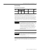
Status Byte
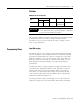
The first byte (bits 0…7) of the first word of I/O data is set aside as
status information. The second byte (bits 8…15) of the first word of
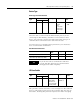
I/O is available for user data. The DNI Input/Output Image is shown
below:
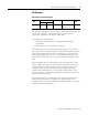
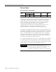
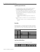
Input Status to Master Device
The Input Status Byte provides the following information.
Word Input/Output Image
Series A Series B
0 0 Data (bits 8…15) Status Byte (bits 0…7)
1 1 Data Most Significant Byte (MSB) Data Least Significant Byte (LSB)
2 2 Data MSB Data LSB
3 3 Data MSB Data LSB
↓↓↓ ↓
14 30 Data MSB Data LSB
15 31 Data MSB Data LSB
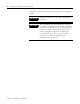
Function n/a Output Buffer Overdrive n/a
Bit Number76 543210