
Owner manual

128
Publication 1761-IN001B-EN-P - July 2007
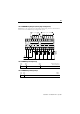
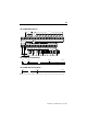
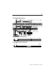
Note: See the 1761-L32AWA wiring diagram on page 114 for relay output voltage range.
NOT
USED
NOT
USED
VAC
VDC
O/0
VAC
VDC
O/1
DC
24V+
O/2 O/3 O/4 O/5 O/6
DC
24V–
O/8O/7 O/9 O/10 O/11
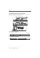
I/9 I/10
DC
COM
I/0 I/1 I/2 I/3 I/4 I/5 I/6 I/7 I/8 I/11 I/12 I/13 I/14 I/15 I/16 I/17 I/18
DC
COM
I/19
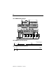
NOT
USED
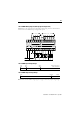
VDC
Com
VDC
14–30 VDC
VDCVDC
Com
14–30 VDC
DC IN
+ 24V –
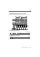
CR
VDC
VDC
COM
SUPR
SUPR
SUPR
SUPR
SUPR
SUPR
SUPR
SUPR
SUPR
SUPR
CRCR
CR
CR
CR
SUPR
SUPR
1761-L32BBB Wiring Diagram (Sinking Input Configuration)
Note: Refer to the configurations in the Sinking and Sourcing section of the Installation
Instructionson for additional input configuration options.
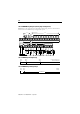
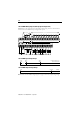
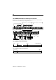
0V dc 5V dc 14V dc
0V dc 5V dc 14V dc
On
?
Off
0V dc 26.4V dc20.4V dc
Operating Range
?
26.4V dc at 55˚C (131˚F)
30V dc at 30˚C (86˚F)
1761-L32BBB Input Voltage Range
1761-L32BBB Output Voltage Range