
Owner manual


115
Publication 1761-IN001B-EN-P - July 2007
VDC
Com
I/0 I/1 I/2 I/3 I/4 I/5
DC OUT
+ 24V –
DC
COM
DC
COM
VDC VDC
Com
VDC
14–30 VDC
L1
VAC
VDC
O/0
VAC
VDC
O/1
VAC
VDC
O/2 O/3
VAC
VDC
L2/N
85–264 VAC
VAC
VAC
COM
NOT
USED
NOT
USED
NOT
USED
NOT
USED
NOT
USED
NOT
USED
NOT
USED
SUPR
SUPR
CR
SUPR
SUPR
CR
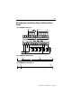
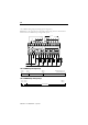
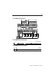
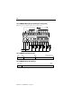
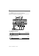
1761-L10BWA Wiring Diagram (Sinking Input Configuration)
Note: Refer to the configurations in the Sinking and Sourcing section of the Installation
Instructionson for additional input configuration options.
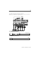
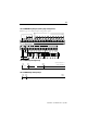
0V dc 5V dc 14V dc
On
?
Off
26.4V dc at 55˚C (131˚F)
30V dc at 30˚C (86˚F)
0V dc 5V dc
14V dc
0V dc 125V dc5V dc
0V ac 264V ac5V ac
?
Operating Range
1761-L10BWA Input Voltage Range
1761-L10BWA Output Voltage Range