
Programmer (HHP) User guide


Appendix E
Application Example Programs
E–26
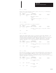
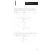
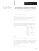
Data Files
Address 15 Data 0
N7:0 0000 0000 0000 0000
N7:1 0000 0000 0000 0100
N7:2 0000 0000 0000 0010
N7:3 0000 0000 0000 0001
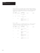
Data Table
Address Data (Radix=Decimal)
N7:0 0 421006000 1500 3000
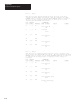
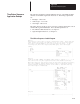
Time Driven Sequencer Instruction List Program
File 2, Rung 0
The function of this rung is called a regenerative timer. Every time the
timer reaches its preset, the DONE bit is set for one scan––this causes
this rung to become FALSE for one scan and resets the timer. On the
following scan, when this rung becomes TRUE again, the timer begins
timing.
FUN GRAPHIC PARAMETER
CODE SYMBOL MNEMONIC NAME ADDRESS VALUE FORCES
–––– ––––––– –––––––– –––– ––––––– ––––– ––––––
21 |–]/[– LDI Timer Enable
T0/DN 0
0 TON Timer
TIMR T0
BASE 0.01
PRE 0001H
ACC 0000H
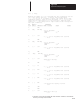
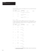
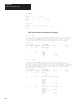
File 2, Rung 1
Controls the RED, GREEN, and YELLOW lights wired to outputs O:0/0 – O:0/2
and controls how long the regenerative timer times between each step.
When this rung goes from false-to-true (by the timer reaching its preset),
the first sequencer changes which traffic light is illuminated and the
second sequencer changes the preset of the timer to determine how long
this next light is illuminated.
FUN GRAPHIC PARAMETER
CODE SYMBOL MNEMONIC NAME ADDRESS VALUE FORCES
–––– ––––––– –––––––– –––– ––––––– ––––– ––––––
20 |–] [– LD Step SQO
T0/DN 0
152 SQO RED, GREEN and YELLOW lights
FILE #N0
MASK 0007H
DEST O0
CTRL R0
LEN 0003H
POS 0000H
152 SQO Timer presets for each light
FILE #N5
MASK FFFFH
DEST T0.PRE
CTRL R1
LEN 0003H
POS 0000H