
Programmer (HHP) User guide

Chapter 2
Wiring
Y
our Controller
2–6
The following pages show the wiring diagrams, discrete input voltage ranges
and discrete output voltage ranges. Controllers with dc inputs can be wired
as either sinking or sourcing configurations. (Sinking and sourcing does not
apply to ac inputs.)
Important:
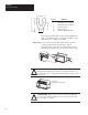
This symbol denotes a functional earth ground terminal
which provides a low impedance path between electrical circuits
and earth for non-safety purposes, such as noise immunity
improvement.
!
ATTENTION: The 24V dc sensor power source should not be
used to power output circuits. It should only be used to power
input devices (e.g. sensors, switches). Refer to page 1–3 for
information on MCR wiring in output circuits.
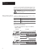
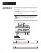
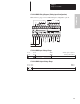
1761-L16AWA Wiring Diagram
NOT
USED
NOT
USED
79–132V ac
L2/N
L1
VAC
VDC O/0
VAC
VDC O/1
VAC
VDC O/2 O/3
VAC
VDC O/4
L2/N
O/5
85–264 VAC
CR CR
I/9I/0 I/1 I/2 I/3 I/4 I/5 I/6 I/7 I/8
AC
COM
AC
COM
L1
CR
L2/N L1
VAC
1
V
AC 1
COM
V
AC 2
V
AC 2
COM
VDC 1
VDC 1
COM
VDC 2
VDC 3
COM
79–132V ac
VAC
VDC
CR
VDC 2
COM
VDC 3
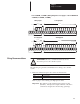
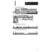
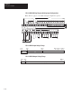
1761-L16AWA
Input V
oltage Range
0V ac 20V ac
132V ac
79V ac
On
?
Off
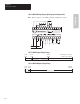
1761-L16AWA
Output V
oltage Range
0V dc 125V dc5V dc
0V ac 264V ac5V ac
?
Operating Range
Wiring Diagrams, Discrete
Input and Output V
oltage
Ranges