
Programmer (HHP) User guide


Chapter 14
Using High-Speed Counter Instructions
14–14
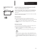
When a low preset is reached, the:
• LP bit is set.
• High-speed counter interrupt file (file 4) is executed if the interrupt is
enabled. The IL bit is set and the IH, IN, and IV bits are reset.
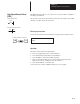
An overflow occurs when the hardware accumulator transitions from
+32,767 to –32,768. When an overflow occurs, the:
• OV bit is set.
• High-speed counter interrupt file (file 4) is executed if the interrupt is
enabled. The IV bit is set and the IH, IL, and IN bits are reset.
An underflow occurs when the hardware accumulator transitions from
–32,768 to +32,767. When an underflow occurs, the:
• UN bit is set.
• High-speed counter interrupt file (file 4) is executed if the interrupt is
enabled. The IN bit is set and the IH, IL, and IV bits are reset.
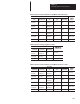
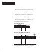
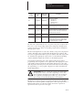
The following tables summarize what the input state must be for the
corresponding high-speed counter action to occur:
Bidirectional Counter (Encoder)
Input State
High-Speed
Count r ction
Input A (I/0) Input B (I/1) HSC Rung
High-Sp
ee
d
Counter Action
Turning On Off True Count Up
Turning Off Off True Count Down
NA On NA Hold Count
NA NA False Hold Count
NA (Not Applicable)
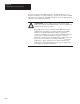
Bidirectional Counter with Reset and Hold (Encoder)
Input State
High-Sp
ee
d
Count r
Input A (I/0) Input B (I/1) Input Z (I/2)
Input Hold
(I/3)
HSC Rung
High-Sp
ee
d
Counter
Action
Turning On Off Off Off True Count Up
Turning Off Off Off Off True Count Down
Off or On NA Off NA NA Hold Count
NA On Off NA NA Hold Count
NA NA Off NA False Hold Count
NA NA Off On NA Hold Count
Off Off On
➀
NA NA Reset to 0
NA (Not Applicable)
➀ The optional hardware high-speed counter reset is the logical coincidence of A x B x Z.