
Programmer (HHP) User guide

Chapter 8
Using Basic Instructions
8–8
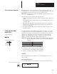
Use an OUT instruction in your ladder program to turn On a bit when rung
conditions are evaluated as true.
An example of a device that turns on or off is an output wired to a pilot light
(addressed as O/4).
OUT instructions are reset when:
• You enter or return to the RRUN, RCSN, or RSSN mode or power is
restored.
• The OUT is programmed within an inactive or false Master Control Reset
(MCR) zone.
• Rung conditions are evaluated as false.
Important: A bit that is set within a subroutine using an OUT instruction
remains set until the subroutine is scanned again.
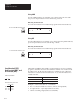
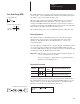
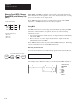
Entering the Instruction
You enter the instruction from within the program monitor functional area.
P
0 0 0
B / 0 0
SET and RST are retentive output instructions. SET can only turn on a bit,
while RST can only turn off a bit. These instructions are usually used in
pairs, with both instructions addressing the same bit.
Your program can examine a bit controlled by SET and RST instructions as
often as necessary.
!
ATTENTION: Under fatal error conditions, physical outputs are
turned off. Once the error conditions are cleared, the controller
resumes operation using the data table value of the operand.
( )
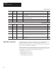
Execution Times (µ
sec) when:
True False
4.43 4.43
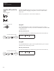
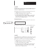
Ladder representation:
Output
(
O
U
T
)
1
OUT
To access the OUT instruction, press:
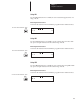
False
4.97
(L)
(U)
Execution Times (µ
sec) when:
True
3.16SET
4.97 3.16RST
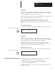
Ladder representation:
S
e
t
(
SET
)
and
Rese
t
(R
ST
)