
Programmer (HHP) User guide

8
Chapter
8–1
Using Basic Instructions
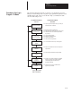
This chapter contains general information about basic instructions and
explains how they function in your application program. Each of the basic
instructions includes information on:
• what the instruction symbol looks like
• typical execution time for the instruction
• how to use the instruction
• how to enter the instruction
In addition, the last section contains an application example for a paper
drilling machine that shows the basic instructions in use.
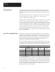
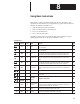
Bit Instructions
HHP
Display
Mnemonic
Function
Code
Name Purpose Page
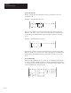
LD 20 Load
Examines a bit for an On condition. It is the first normally open instruction
in a rung or block.
8–3
LDI 21 Load Inverted
Examines a bit for an Off condition. It is the first normally closed instruction
in a rung or block.
8–4
AND 22 And
Examines a bit for an On condition. It is a normally open instruction placed
in series with any previous input instruction in the current rung or block.
(This differs from the AND output instruction discussed in chapter 10.)
8–3
ANI 23 And Inverted
Examines a bit for an Off condition. It is a normally closed instruction
placed in series with any previous input instruction in the current rung or
block.
8–4
OR 24 Or
Examines a bit for an On condition. It is a normally open instruction placed
in parallel with any previous input instruction in the current rung or block.
(This differs from the OR output instruction discussed in chapter 11.)
8–3
ORI 25 Or Inverted
Examines a bit for an Off condition. It is a normally closed instruction
placed in parallel with any previous input instruction in the current rung or
block.
8–4
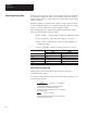
LDT
LDT 26 Load True Represents a short as the first instruction in a rung or block. 8–6
ORT
ORT 27 Or True
Represents a short in parallel with the previous instruction in the current
rung or block.
8–6
OSR
LD OSR 28
On
e
-Shot
Risi
ri ers a e i e e e
8–7
OSR
AND OSR 29
On
e
-Shot
Rising
T
ri
gg
ers
a
on
e
-t
i
m
e
e
v
e
nt.
8–7
( )
OUT 40
Output (Output
Energize)
Represents an output driven by some combination of input logic.
Energized (1) when conditions preceding it permit power continuity in the
rung and de-energized after the rung is false.
8–8
(L)
SET 41
Set (Output
Latch)
Turns a bit on when the rung is executed and this bit retains its state when
the rung is not executed or a power cycle occurs.
8–8
(U)
RST 42
Reset (Output
Unlatch)
Turns a bit off when the rung is executed and this bit retains its state when
the rung is not executed or when power cycle occurs.
8–8
Continued on following page